


OM-225 590 Page 31
ether1 7/96 − 153 382-A / 225 543 / 804 289-A
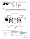
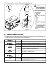
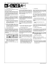
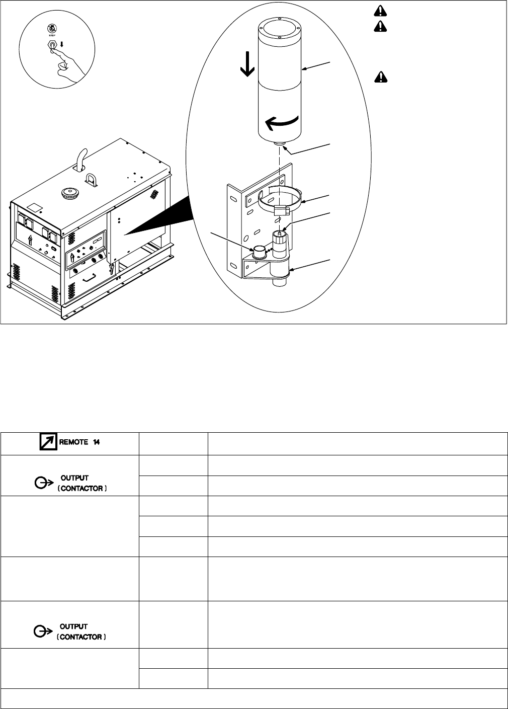
! Stop engine.
! Improper handling or expo-
sure to ether can harm your
health. Follow manufactur-
er’s safety instructions on
cylinder.
! Do not use Ether Starting Aid
while engine is running.
Open right side door.
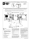
1 Ether Cylinder
2 Nozzle
Remove cover and clean cylinder
nozzle.
3 Clamp
4 Fitting
5 Cap
6 Valve
Remove cap and clean fitting.
Install cylinder on fitting. Tighten
clamp.
. After installing cylinder, wait at
least 10 minutes before using
to let ether particles settle and
prevent atomizer plugging.
Put cap on fitting when cylinder is
removed.
5-16. Installing Ether Cylinder (Optional Ether Starting Aid)
1
2
3
4
6
5
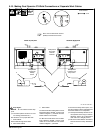
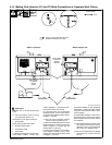
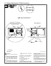
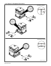
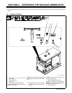
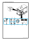
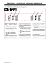
5-17. Remote 14 Receptacle Information
. Place Welder Selector switch in Welder A/Welder B position (dual operator mode) for both remote receptacles to work. Welder A (left) remote
receptacle output contactor and control is disabled when switch is in Welder B position.
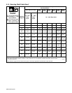
Socket* Socket Information
24 VOLTS AC
A 24 volts ac. Protected by supplementary protectors CB5 and CB6.
B Contact closure to A completes 24 volts ac contactor control circuit.
REMOTE
C Output to remote control; +10 volts dc in CV, 0 to +10 volts dc in CC.
REMOTE
OUTPUT
CONTROL
D Remote control circuit common.
CONTROL
E 0 to +10 volts dc input command signal from remote control.
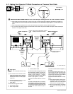
A/V
AMPERAGE
VOLTAGE
F
H
Current feedback; 0 to +10 volts dc, 1 volt per 100 amperes.
Voltage feedback; +1 volts dc per 10 arc volts.
115 VOLTS AC
I
J
115 volts, 15 amperes, 60 Hz ac. Protected by supplementary protectors CB5 and
CB6.
Contact closure to I completes 115 volts ac contactor control circuit.
GND
K Chassis common.
GND
G Circuit common for 24 and 115 volts ac circuits.
*The remaining sockets are not used.