


. A complete Parts List is available at www.MillerWelds.com
OM-1327 Page 30
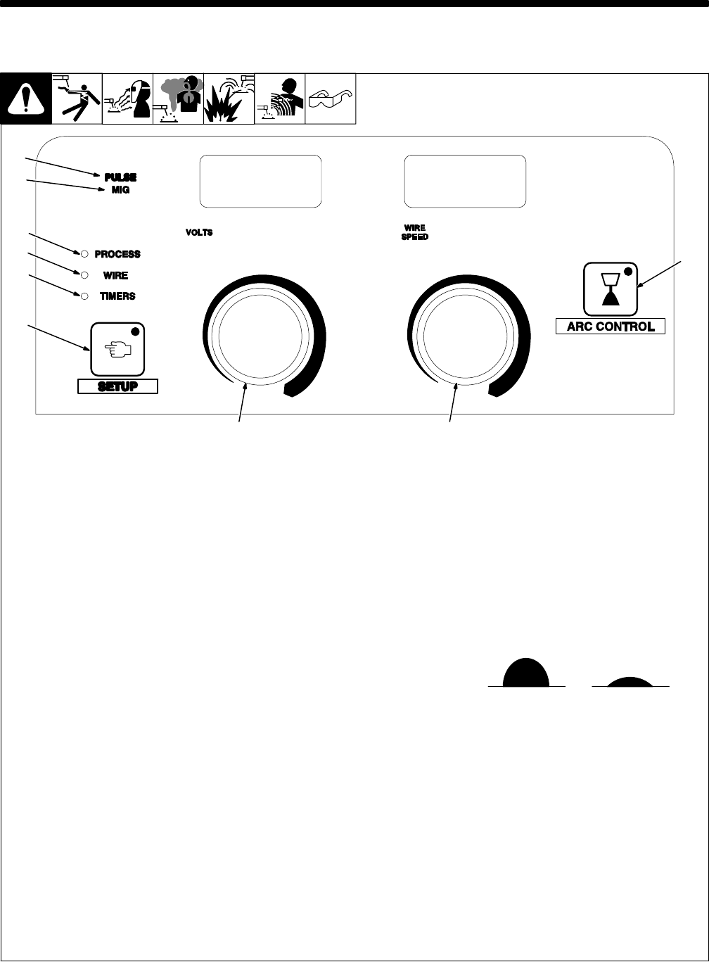
SECTION 5 − PROGRAMMING
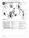
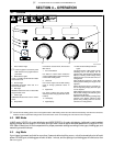
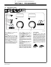
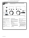
5-1. MIG Welding Mode
When the MIG light (2) is illuminated, the
unit is in MIG Welding mode.
SETUP
To enter MIG welding mode, depress the
SETUP (6) button once to go to GUN
selection. Rotate the right knob (9) to select
the gun being used. Select MIG for standard
MIG gun, or select XR-A, EDGE, PYTH alpr
for push pull guns, or SPL for spoolgun.
Depress SETUP (6) a second time to
illuminate the PROCESS (3) light. Rotate
right knob (9) until MIG is displayed (for MIG
only units NOT USED will be displayed).
Depress SETUP (6) button again to
illuminate the WIRE (4) light. This menu is
not used in MIG Welding mode.
Depress SETUP (6) button again to
illuminate TIMERS (5) light. For description
of the TIMERS, refer to TIMERS menu
(see Section 5-3)
If crater fill function menus are enabled,
TIMERS light will stay on to allow for adjust-
ment of crater parameters and timers (see
Section 5-6).
Depress SETUP (6) button again to exit
menus and enter MIG welding mode.
OPERATION
Adjust welding Voltage with left knob (8)
and Wire Feed Speed with right knob (9).
Refer to MIG welding chart for proper
Voltage and Wire Feed Speed setting in
reference to material type, material
thickness, wire, and gas (see Section 4-9).
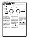
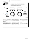
ARC CONTROL
MIG welding mode: Depress ARC
CONTROL (7) button to enter Arc control
menu and INDU will appear on the left
display and the corresponding setting will
appear on the right display. Adjust right
knob (9) to adjust inductance setting. In
MIG welding mode the Arc control is an
inductance control from 0-99. Refer to MIG
welding chart for suggested Inductance
setting for the wire and gas types being
used (see Section 4-9). Changing the
inductance will change the fluidity of the
puddle.
Low Inductance High Inductance
Weld Bead Weld Bead
(0 setting) 99 setting
Ref. 213 935-A
1
7
98
2
3
4
5
6