


. A complete Parts List is available at www.MillerWelds.com
OM-1327 Page 43
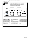
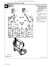
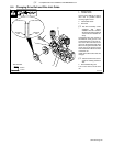
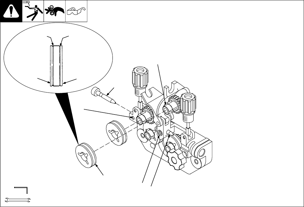
6-4. Changing Drive Roll and Wire Inlet Guide
1 Securing Screw
2 Inlet Wire Guide
Loosen screw. Slide tip as close to
drive rolls as possible without
touching. Tighten screw.
3 Intermediate Guide
4 Drive Roll
. The drive assembly comes
equipped with factory
installed .035/.045 combina-
tion drive rolls. Be sure that all
4 drive rolls are installed cor-
rectly.
Combination drive rolls consist of
two different sized grooves. The
stamped markings on the end sur-
face of the drive roll refers to the
groove on the opposite side of the
drive roll. The groove closest to the
carrier gear is the groove for the
wire size viewed on the end surface
of the drive roll.
Install correct drive roll for wire size
and type.
. U-Grooved drive rolls are re-
quired for feeding aluminum
wire.
5 Drive Roll Securing Nut
Turn nut one click to secure drive
roll.
1
2
4
5
Tools Needed:
5/64 in
7/16 in
802 520-B
1
3
Stamped
.035
Stamped
.045
.045 Groove
.035 Groove