


OM-230 009 Page 15
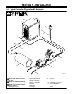
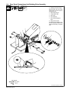
. The illustration shows remote control connected through the wirefeeder.
The wirefeeder is not connected to the power source output..
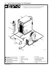
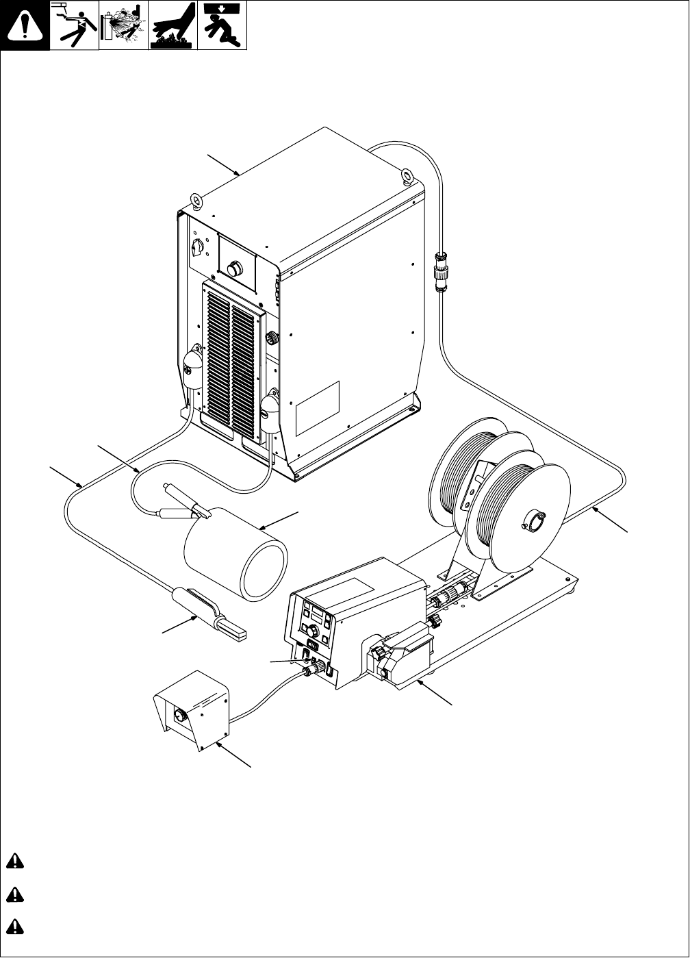
5-3. Typical Connection Diagram For Stick Equipment
804 780-A
! Do not mount feeder on top of pow-
er source.
! Do not put feeder where welding
wire hits cylinder.
! Do not move or operate equipment
when it could tip.
1 Welding Power Source
2 Negative (−) Weld Cable
3 Positive (+) Weld Cable
4 Workpiece
5 Electrode Holder
6 Hand Control
7 Wire Feeder
8 14-Pin Feeder Control Cable
9 Remote Switch To STICK/TIG
. Maximum cable length not to exceed
150 feet.
7
6
8
1
3
2
4
5
9