


OM-230 009 Page 24
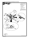
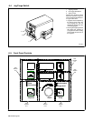
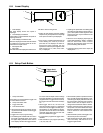
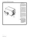
6-8. Lower Display
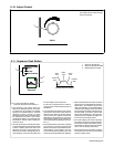
1 Lower Display
The lower display shows wire speed or
amperage.
2 Lower Display Push Button
Press button to choose between wire speed or
amperage functions.
3 Lower Display Push Button LED
The lower display push button LED illuminates
to indicate that wire feed speed can be ad-
justed with the Adjust control.
4 Wire Speed LED
5 Amps LED
The LEDs below the display illuminate to indi-
cate which value is being shown.
• At idle, the wire speed for the active welding
sequence may be adjusted or the amperage
of the previous weld may be displayed.
• If the unit is in a welding state that does not
involve feeding wire, such as pre−flow or
post−flow, the unit displays the weld se-
quence wire speed; otherwise, the wire
speed of the active sequence segment of the
weld program (run−in, start, weld, crater,
etc.), is displayed.
• Adjusting wire speed while in a welding state
will modify the weld segment of the weld pro-
gram. Wire speed for other segments of the
weld program can only be modified via the
Sequence menu.
• When the unit is displaying amperage, the
Amps LED illuminates. While in a welding
state, the actual weld current is shown.
While idle, the amperage at the end of the
previous welding state is shown.
• Amperage values of less than 5 Amps are
displayed as “−−−−”.
2
Wire Speed Amps
1
5
4
3
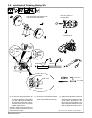
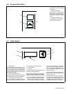
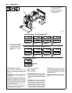
6-9. Setup Push Button
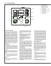
1 Setup Push Button
Press button to choose between trigger hold
or dual schedule functions.
2 Setup Push Button LED
3 Trigger Hold LED
4 Dual Schedule LED
• When the Setup button is pressed, the Set-
up push button LED flashes and the Trigger
Hold LED flashes.
• Trigger hold is a per program setting.
• The flashing LED indicates that the unit is in
the trigger hold display mode. In this mode
the upper display indicates HOLD and the
lower display indicates the trigger hold sta-
tus On/Off. Use the Adjust control to change
the trigger hold status or press the lower dis-
play push button. If trigger hold is turned On,
the trigger hold LED illuminates and stays
On.
• When trigger hold is On, the user must
press and hold the trigger for a predefined
amount of time (the trigger hold delay time−
see Section 6-12), then release it for the trig-
ger hold function to be active. To shut off the
weld when trigger hold is On, the user must
press and release the trigger.
• If a weld time is programmed, trigger hold is
disabled.
• Dual Schedule is a per program pair setting
(1,2) (3,4) (5,6) (7,8).
• When the Setup button is pressed a second
time, the dual schedule LED flashes. In this
mode the upper display indicates DUAL and
the lower display indicates dual schedule
status On/Off. Use the Adjust control to
change the dual schedule status if desired.
• Pressing the Setup button again exits the
Setup mode. The dual schedule LED stops
flashing to indicate the dual schedule status
is Off, or remains on if dual schedule was
enabled.
• While in the Setup mode, if the trigger is acti-
vated, Setup mode is terminated.
• Dual schedule and trigger select cannot be
used concurrently. See Section 6-12 for
Trigger Program Select.
Trigger Hold
Setup
Dual Schedule
1
2
3
4