


OM-230 009 Page 27
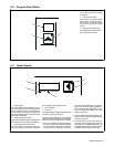
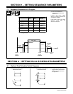
Range Locks
Range locks are indicated by “LOCK” in the
upper display for wire speed or “LOCK” in
the lower display for voltage range.
In a MIG program, the voltage range lock
ranges from +/− 0 to 10 volts.
In a pulse program, the trim range lock
ranges from +/− 0 to 100.
The wire speed range lock ranges from +/−
0 to 195 IPM.
Locks are program dependent and wire
speed locks are independent from voltage/
trim command locks (i.e. you can have a
wire speed lock with or without locking the
voltage/trim command and vice versa).
Press the Upper Display Pushbutton to se-
lect Voltage/Trim Command Range Locks.
Press the Lower Display Pushbutton to se-
lect Wire Speed Range Locks.
To set a Voltage/Trim Command Range
Lock, you must choose the type of com-
mand being locked, voltage or trim based
on the type of weld process selected at the
power source. This is done by repeatedly
pressing the Upper Display Pushbutton to
cycle between OFF, T (trim) or V (voltage),
as indicated on the Upper Display.
Use the adjust knob to set the range value.
Once any program has a lock enabled, the
remaining programs with all locks “OFF”
will not be accessible. To enable additional
programs, set the lock values for one or
more Voltage/Trim Command or Wire
Speed to appropriate ranges for each pro-
gram.
Only one of the values needs to be set to
enable the program. For example, setting a
Trim of 100 and leaving the Wire Speed at
OFF will allow the welder to adjust the Wire
Speed to full range
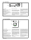
Wire Feed Speed Units
Wire feed speed setting indicated by “WFS”
in the upper display is set to “IPM” inches−
per−minute or ”MPM” meters−per−minute.
This setting is independent of the program
selected.
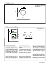
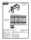
Software Revision Level
• The unit displays the software version
being used by the interface PCB (PC20).
• When the Setup button is pressed again,
the menu repeats.
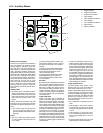
Code
Upon leaving the auxiliary menu, the user is
asked if a password code, indicated by
“CODE” in the top display should be acti-
vated.
By default the code is “OFF” in the lower
display. The user may enter a numerical
password between 0 and 999 by turning the
Adjust control.
If a code is set, when the user re-enters the
auxiliary menu, the password code must be
selected to gain access to the auxiliary
menu. Press Setup and Sequence buttons
simultaneously to enter the auxillary menu.
A failed attempt returns the user to the weld
screen and a counter is incremented. A
counter in the program display shows the
number of incorrect attempts. The user has
five attempts to enter the correct password
code before being locked out of the auxilia-
ry menu, indicated by “LOCK” in the lower
display.
The power may be cycled to continue weld-
ing, but the user will remained locked out of
the auxiliary menu.
The counter can be reset in the weld screen
by pressing the Program, Sequence, upper
display, and Set-up push buttons simulta-
neously. Resetting the counter is indicated
by “CODE” in the upper display and “RSET”
in the lower display. Pressing the Program,
Sequence, upper display, and Set-up push
buttons simultaneously again resets the
counter to 0.
To reset the password, follow the directions
under Reset To Factory Settings at the be-
ginning of this section. Note: this will reset
all settings and programs to the factory de-
faults.