


OM-230 009 Page 26
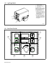
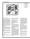
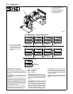
6-12. Auxiliary Menus
Program
Start
Crater
Pre/Postflow
Trigger Hold
Adjust
V/Trim Time (sec)
Wire Speed Amps
Sequence Setup
Dual Schedule
3
4
2
9
8
1
5
7
6
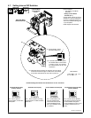
1 Program Display
2 Program Push Button
3 Sequence Push Button
4 Upper Display
5 Upper Display Push Button
6 Lower Display
7 Lower Display Push Button
8 Adjust Control
9 Setup Push Button
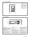
Reset To Factory Settings
A reset menu is displayed if the following
four push buttons are pressed simulta-
neously: Program, Sequence, upper dis-
play, and Setup. The upper display indi-
cates “WIPE” . The lower display indicates
“OFF”. The lower push button is active indi-
cating that the Adjust control can be used to
change the unit to “WIPE ON”. When “WIPE
ON” is set, if the original four push buttons
are simultaneously pressed a second time,
the unit will reset all settings to factory de-
fault except the arc time and arc cycle
counts. If a reset is not desired, set the dis-
play to “WIPE OFF” and simultaneously
press the Program, Sequence, upper dis-
play, and Setup push buttons to exit the re-
set menu.
Auxiliary Menu
• An auxiliary menu is provided if both the
Sequence and Setup push buttons are
pressed simultaneously. The Setup push
button and sequence push button LEDS
flash when the auxiliary menu is dis-
played.
Pushing the Setup push button will step
through the menu. Pushing the sequence
push button will step through the menu in re-
verse.
. The auxiliary menu may be exited at
any time by pressing both the Se-
quence and Setup push buttons simul-
taneously.
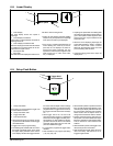
Run-In
• The run-in modes are program specific
(i.e. each program may be set to its own
run-in mode).
The upper display indicates “RUNI”. The
lower display indicates “AUTO”, meaning
the factory set automatic run-in speed is
selected.
Pressing the lower display button allows
manual setting of the run-in wire speed.
Speed may be adjusted from 10% to
100% of weld wire speed.
Pressing the lower display button again
allows disabling of the run-in feature.
When the lower display indicates “OFF”,
run-in is disabled.
Burnback
Burnback time and voltage can be specified
when the lower display indicates “BURN”
and the upper display indicates the burn-
back time or voltage. The Adjust control is
used to set the desired burnback time or
voltage. Burnback settings are program
specific. The active program is displayed in
the Program display and can be adjusted
(see Section 6-6).
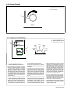
Trigger Hold Setup
Trigger hold delay time is indicated by
”HOLD” in the lower display and the hold
delay time in the upper display. The adjust
control can be used to specify a new delay
time for trigger hold. Trigger hold delay time
is the minimum amount of time the trigger
must be held for trigger hold to work when
the trigger is released (the trigger hold func-
tion must be on). For example, if a trigger
hold delay time of 2.0 seconds is defined,
the operator must hold the trigger for at least
2 seconds before releasing it in order for the
trigger hold function to work. Once the trig-
ger hold function is in effect, the wire feeder
will stay On until the trigger is pressed and
released again.
• There is an additional function built in
called ”maximum trigger hold time” which
is the maximum length of time the trigger
can be held and the trigger hold function
still work when the trigger is released (the
trigger hold function must be on). The
maximum trigger hold time is set at 4.0
seconds after the trigger hold delay time.
For example, if a trigger hold delay time of
2.0 seconds is defined, and the operator
held the trigger in for more than 6.0 sec-
onds, the trigger hold function would not
be in effect and the wire feeder would stop
when the trigger is released.
Trigger Program Select
The upper display shows “TSEL”. Lower
display shows “On” or “Off”. The Adjust con-
trol is used to select either “On” or “Off”.
Trigger Program Select allows the operator
to select programs by clicking the trigger
(pulling and releasing the trigger in a maxi-
mum of 0.2 seconds). The feeder will switch
between any programs that have a mini-
mum of 0.2 seconds of preflow time set in
the weld sequence.
• Any combination of programs may be
used.
• If only programs 1 and 3 have a minimum
of 0.2 seconds of preflow time, clicking
the trigger will toggle between programs
1 and 3.
• If only programs 1, 2, and 4 have a mini-
mum of 0.2 seconds of preflow time, click-
ing the trigger will switch from 1 to 2 to 4
to 1 to 2.
• Trigger Program Select cannot be used
while welding or with Dual Schedule.