


OM-222 166 Page 13
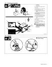
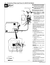
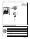
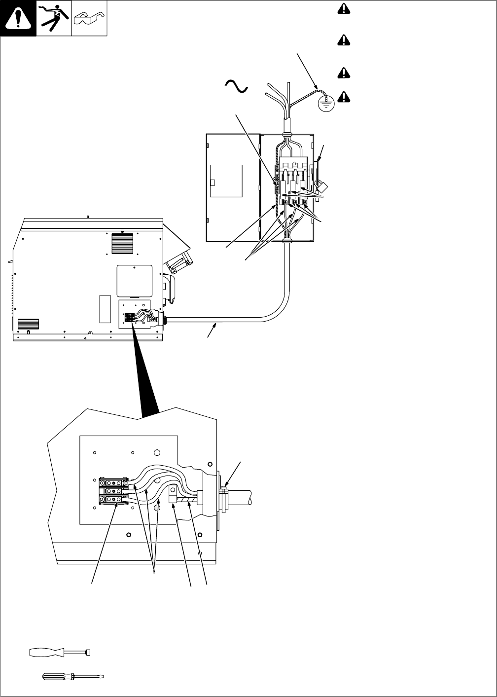
4-5. Connecting 3-Phase Input Power For 460/575 Volt Models
803 994-C
3/8 in
Tools Needed:
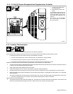
! Installation must meet all National
and Local Codes − have only quali-
fied persons make this installation.
! Disconnect and lockout/tagout in-
put power before connecting input
conductors from unit.
! Make input power connections to
the welding power source first.
! Always connect green or green/
yellow conductor to supply
grounding terminal first, and never
to a line terminal.
. The circuitry in this unit automatically
adapts the power source to the
primary voltage being applied. Check
input voltage available at site. This
unit can be connected to either 460 or
575 VAC input power.
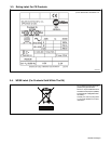
See rating label on unit and check input
voltage available at site.
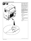
1 Input Power Conductors (Customer
Supplied Cord)
Select size and length of conductors using
Section 4-4. Conductors must comply with
national, state, and local electrical codes.
If applicable, use lugs of proper amperage
capacity and correct hole size.
Welding Power Source Input Power
Connections
2 Strain Relief
Route conductors (cord) through strain re-
lief and tighten screws.
3 Machine Grounding Terminal
4 Green Or Green/Yellow Grounding
Conductor
Connect green or green/yellow grounding
conductor to welding power source
grounding terminal first.
5 Welding Power Source Line
Terminals
6 Input Conductors L1 (U), L2 (V) And
L3 (W)
Connect input conductors L1 (U), L2 (V)
and L3 (W) to welding power source line
terminals.
Close and secure access door on welding
power source.
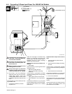
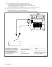
Disconnect Device Input Power
Connections
7 Disconnect Device (switch shown in
OFF position)
8 Disconnect Device (Supply)
Grounding Terminal
Connect green or green/yellow grounding
conductor to disconnect device grounding
terminal first.
9 Disconnect Device Line Terminals
Connect input conductors L1 (U), L2 (V)
And L3 (W) to disconnect device line
terminals.
10 Over-Current Protection
Select type and size of over-current
protection using Section 4-4 (fused dis-
connect switch shown).
Close and secure door on line disconnect
device. Remove lockout/tagout device,
and place switch in the On position.
GND/PE Earth Ground
7
2
10
8
4
9
1
6
3
4
3
6
5