


OM-222 166 Page 20
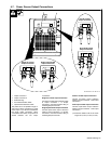
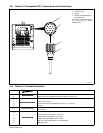
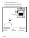
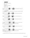
9. The following describes the thermocouple routing from work to power source.
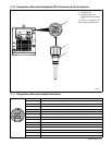
S Type K thermocouple wire (two wire) is attached directly to the workpiece using a
Thermocouple Attachment Unit (see next section for information on attaching thermocouples).
S The other end is fitted with a 2-pin type K connector.
S The 2-pin connector plugs into the 3-pin composite extension cable. The extension cable has a six-channel
block of 3-pin female connectors. The pin size locates the position of the 2-pin connector on the extension.
S The extension cable contains six, 3-wire bundles of shielded cable.
S The 3-pin male extension cable plugs into the 3-pin female connector on the front of the power source.
804 320-A
1
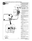
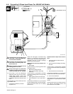
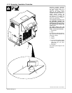
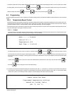
For temperature control mode, the power
source must have (as a minimum) one
thermocouple connected to receptacle
TC1. If multiple thermocouples are desired,
either use individual thermocouple plugs or
the thermocouple extension cable.
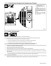
To connect thermocouples to the power
source, proceed as follows:
. Do NOT weld thermocouples to work-
piece while thermocouple cable is con-
nected to the power source.
Turn Off power source.
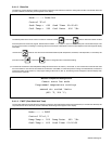
1 Power Source
2 Thermocouple Receptacles
3 Individual Thermocouple Extension
Cable
4 Multiple Thermocouple Extension
Cable
Align plug pin(s) with receptacle socket(s)
and push plug into receptacle.
2
3
4