


OM-222 166 Page 46
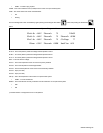
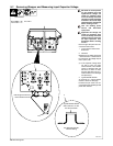
9-7. Removing Wrapper and Measuring Input Capacitor Voltage
! 900 Volts dc can be present
on the capacitor bus and
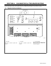
significant DC voltage can
remain on capacitors after
unit is Off. Always check the
voltage on inverter assembly
as shown to be sure the input
capacitors have discharged
before working on unit.
! Turn Off welding power
source, and disconnect
input power.
! Significant DC voltage can
remain on capacitors after
unit is Off. Always check the
voltage as shown to be sure
the input capacitors have
discharged before working
on unit.
Remove right side panel and dis-
connect fan motor FM3.
1 Current Source Interconnect
Board PC4
2 Voltmeter
Measure the dc voltage across the
+ bus terminal and − bus terminal on
PC4 as shown until voltage drops to
near 0 (zero) volts.
. If the capacitor voltage does
not drop to near zero after
several minutes, use a bleeder
resistor of between 200 and
500 ohms, at least 10 watts,
and #16 AWG 600 volts ac in-
sulation rated wire to discharge
the capacitor(s).
3 Typical Bleeder Resistor
An example of a typical bleeder
resistor is shown on this page.
Proceed with job inside unit. Re-
connect FM3 and reinstall right side
panel when finished.
Tools Needed:
5/16, 3/8 in
804 519-B
1
2
+ lead to right bus terminal,
− lead to left bus terminal
3
Typical Bleeder Resistor
#16 AWG 600 Volts AC
Insulation Rating
200 to 500 ohm, 10 watt
wire wound resistor