


OM-222 166 Page 23
SECTION 5 − COMPONENTS AND CONTROLS
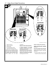
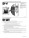
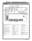
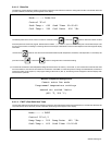
5-1. Controls
. When a control panel button is pushed
the yellow lamp lights to indicate ac-
tivation.
1 Power Switch
Use switch to turn power source On and
Off.
2 TC1−4 Temperature Display
Provides temperature display of thermo-
couples 1 through 4.
3 Control Thermocouple LED’s
LED’s indicate which thermocouples (1−4)
are used to control the heating process.
4 Temperature Units LED’s
LED’s indicate units for temperature mea-
surements (°F or ° C).
5 Fault LED
LED lights to indicate a system fault condi-
tion.
6 Limit LED
LED lights to indicate a system limit condi-
tion.
7 Heat On LED
LED lights to indicate the power source out-
put is energized.
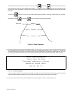
8 Stop Button
Use button to stop a heating process.
9 Hold Button
Use button to hold a heating process.
10 Run Button
Use button to run a heating process.
11 Cursor Button
Use button to move selection cursor in the
4 x 40 LCD display (item 18).
12 Program Button
Use button to program the process control.
13 Run Status Button
Use button to display real time operating
status.
14 Parameter Button
Use button to display real time power
source operating parameters.
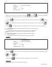
15 Cooler Button
Use button to turn cooler On and Off.
16 Increase Button
Use button to increase values in set-up
screen.
17 Decrease Button
Use button to decrease value in program
screen.
18 4 x 40 LCD Display
Displays programming, runs status, pa-
rameter, fault and limit conditions, and trou-
bleshooting guide.
19 Thermocouple Input Receptacles
Use receptacles for type K thermocouple
inputs.
803 995-B
1
15
14
13
12
17
16
1811891076543
2
19