


OM-222 166 Page 19
803 993-C
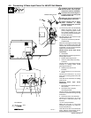
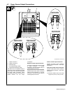
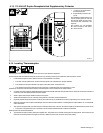
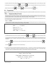
4-13. 115 Volt AC Duplex Receptacle And Supplementary Protector
1 115 VAC 2.5 A Single-Phase
AC Receptacle RC1
2 Supplementary Protector CB1
(2.5 A)
The receptacle supplies nominal 115
volts ac auxiliary power for use with
the optional digital recorder. Maxi-
mum output from receptacle is 2.5
amperes.
CB1 protects 115 volt receptacle
RC1 from overload. If CB1 opens,
RC1 does not work.
1
2
12
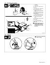
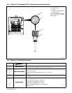
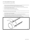
4-14. Locating Thermocouples
Thermocouple location is one of the most critical steps in the Heat Treatment Operation.
Thermocouples shall be located as follows to provide a survey of heating uniformly and enable time and temperature control:
1. Locate thermocouples to ensure that the full area of the heat band is monitored.
S The code normally specifies the number of thermocouples to be used based on the pipe diameter.
S The control thermocouple is placed in the plane of the weld (center of the heat zone).
S The control thermocouple is placed at the top of the pipe in a standard pipe joint configuration. In other
applications, the thermocouple should be located in the hottest portion of the weldment to be stress relieved.
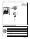
2. Consider all nozzles and other welded attachments that cause potential heat sinks through metal mass or cold spots due to heat convection or
conduction, and have additional thermocouples applied.
3. Attach a spare thermocouple beside control thermocouples.
4. Attach thermocouples to ensure uniformity of temperature in both thin and thick workpieces.
5. Physically inspect all thermocouples for continuity and mark them by an identification number corresponding to the recorder channel.
6. Match the drawings of the workpiece indicating the numerous thermocouple locations, controlling thermocouple locations, etc. to weld identifi-
cation information.
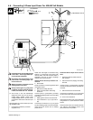
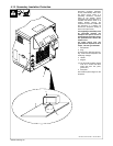
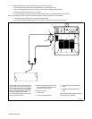
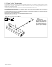
7. The system is equipped with 3-pin thermocouple connections at the front of the unit. Six thermocouples can be attached to the power source.
S The system is equipped with 3-pin connectors to accommodate shielded extension cables. The shielded
cables protect from electrical interference.
8. Type K thermocouple wire has a positive and negative wire. The positive wire is marked as solid yellow or striped yellow. The connector screw
terminals are marked positive and negative. Be sure to attach the wire to the connector with proper polarity.