


OM-224 043 Page 12
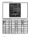
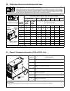
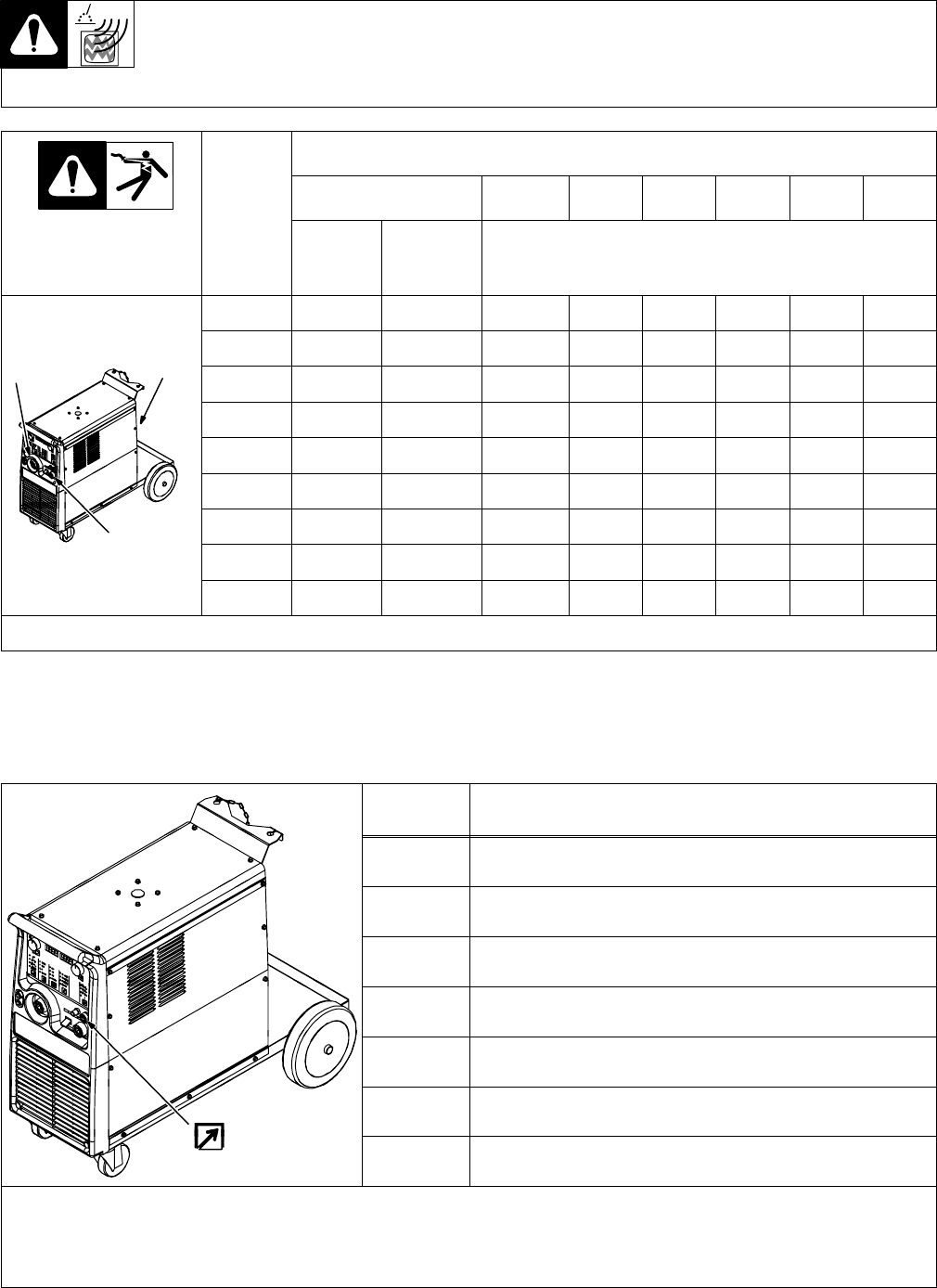
3-6. Weld Output Terminals And Selecting Cable Sizes
Y ARC WELDING can cause Electromagnetic Interference.
To reduce possible interference, keep weld cables as short as possible, close together, and down low, such as on the floor.
Locate welding operation 100 meters from any sensitive electronic equipment. Be sure this welding machine is installed
and grounded according to this manual. If interference still occurs, the user must take extra measures such as moving
the welding machine, using shielded cables, using line filters, or shielding the work area.
Total Cable (Copper) Length In Weld Circuit Not Exceeding
30 m Or Less 45 m 60 m 70 m 90 m 105 m 120 m
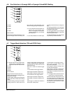
Weld Output Terminals
Welding
Amperes
10 − 60%
Duty
Cycle
60 − 100%
Duty
Cycle
10 − 100% Duty Cycle
100 20 20 20 30 35 50 60 60
Positive
receptacle
TIG/STICK
Negative
receptacle
MIG
150 30 30 35 50 60 70 95 95
p
TIG/STICK
p
MIG
200 30 35 50 60 70 95 120 120
250 35 50 60 70 95 120 2//70 2//70
300 50 60 70 95 120 2//70 2//95 2//95
350 60 70 95 120 2//70 2//95 2//95 2//120
400 60 70 95 120 2//70 2//95 2//120 2//120
Negative receptacle
MIG/TIG/STICK
500 70 95 120 2//70 2//95 2//120 3//95 3//95
MIG/TIG/STICK
600 95 120 2//70 2//95 2//120 3//95 3//120 3//120
// means 2 cables with the same section in parallel.
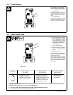
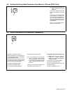
3-7. Remote 7 Receptacle Information (TIG And STICK Only)
Socket Socket Information
1 +10 volts dc supply voltage to remote
2 GND Remote control circuit common
3 IREF 0 to 10 current control signal
4 Not used.
5 UP 0V/10V digital signal
Remote 7
6 Not used.
Remote 7
7 TYPE 0V/10V digital signal
Note: This remote receptacle cannot be used with a standard Miller remote control. A customer supplied remote control is required to use the
remote receptacle.
Some signals can be enabled when TIG or Stick welding. Contact Factory Authorized Service Agent for confirmation.