


OM-224 043 Page 14
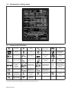
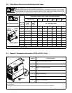
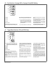
3-10. Electrical Service Guide
Actual input voltage should not exceed ± 10% of indicated required input voltage. If
actual input voltage is outside of this range, output may not be available.
NOTE
50/60 Hz Three Phase
Input Voltage 400
Input Amperes At Rated Output 17
Max Recommended Standard Fuse Rating In Amperes
1
Time-Delay
2
20
Normal Operating
3
25
Min Input Conductor Size In mm
2
,
4
2.5
Max Recommended Input Conductor Length In Meters 41
Min Grounding Conductor Size In mm
2
,
4
2.5
Reference: 1999 National Electrical Code (NEC)
1 Consult factory for circuit breaker applications.
2 “Time-Delay” fuses are UL class “RK5” .
3 “Normal Operating” (general purpose - no intentional delay) fuses are UL class “K5” (up to and including 60 amp), and UL class “H” ( 65 amp and
above).
4 Conductor data in this section specifies conductor size (excluding flexible cord or cable) between the panelboard and the equipment per NEC Table
310.16. If a flexible cord or cable is used, minimum conductor size may increase. See NEC Table 400.5(A) for flexible cord and cable requirements.
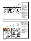
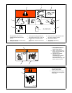
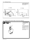
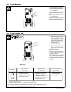
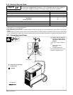
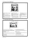
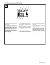
3-11. Connecting Input Power
Y Always connect green/yel-
low wire to supply ground-
ing terminal, never to a line
terminal.
Check input voltage available at
site.
1 Input And Grounding
Conductors
2 Line Disconnect Device
Select type and size of overcurrent
protection using Section 3-10.
Tools Needed:
L1
2
1
L2
L3
Y Always connect grounding
conductor first.
= GND/PE
Green/Yellow