


Installation & Programming Manual FX & VFX “E” Series Inverte r/Charge r Sy ste m Copyright 2003 OutBack Power Systems, Inc.
19009 62
nd
Ave NE, Arlington WA 98223 USA
Page 11 Rev 7.0 07/02/04 Tel 360 435 6030 Fax 360 435 6019
COMPLETE OUTBACK INTEGRATED SYSTEMS
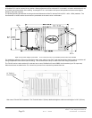
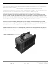
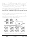
Shown below are complete systems of OutBack FX’s for indoor installations. The system with four FX’s is shown mounted to the
OutBack PSMP (Power System Mounting Plate). The PSMP comes with six 1x20mm thread forming screws for attaching FX’s and
breaker boxes. The use of an external toothed star washer (provided) is required on one screw on each piece of equipment in order to
bite through the powder coating and ensure grounding of all metal components. The system with two FX’s is shown mounted to the
smaller OutBack PS2MP (the “2” in PS2MP refers to the maximum number of FX’s that will fit) power system mounting plate.
The mounting plate will typically need to be bolted to the studs in a wall using at least four 1/4” or 5/16” lag bolts 2” long. In addition to
the mounting plate, these installations are also shown with an OutBack PSDC or PS2DC (DC breaker box), PSAC or PS2AC (AC
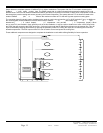
breaker box), FX-DCA (DC Conduit Adapter), FX-DCC (DC Compartment Cover), and the FX-ACA (AC Compartment Adapter). When
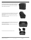
two or more FX’s are installed in close proximity such as in this installation, it may be useful to install one or more 12VDC fans inside
the PSDC that will pressurize the PSDC enclosure – forcing air up through the DC Manifold and down over the external fins. This will
improve the battery charging performance by reducing the possibility of the FX’s limiting the output due to reaching their maximum
allowed temperatures. The AUX outputs of the FX’s can be used to control and power the cooling fans.
These additional components are designed to complete the installation to code while offering flexibility for future expansion.