


Copyright 2003 OutBack Power Systems, Inc. FX & VFX “E” Series Inverter/Charger System Installation & Programming Manual
19009 62
nd
Ave NE, Arlington WA 98223 USA
Tel 360 435 6030 Fax 360 435 6019 Rev 7.0 07/02/04
Page 21
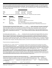
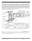
FX SYSTEM CONFIGURATION - 3 PHASE FX SYSTEM
3-Phase FX System
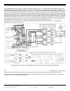
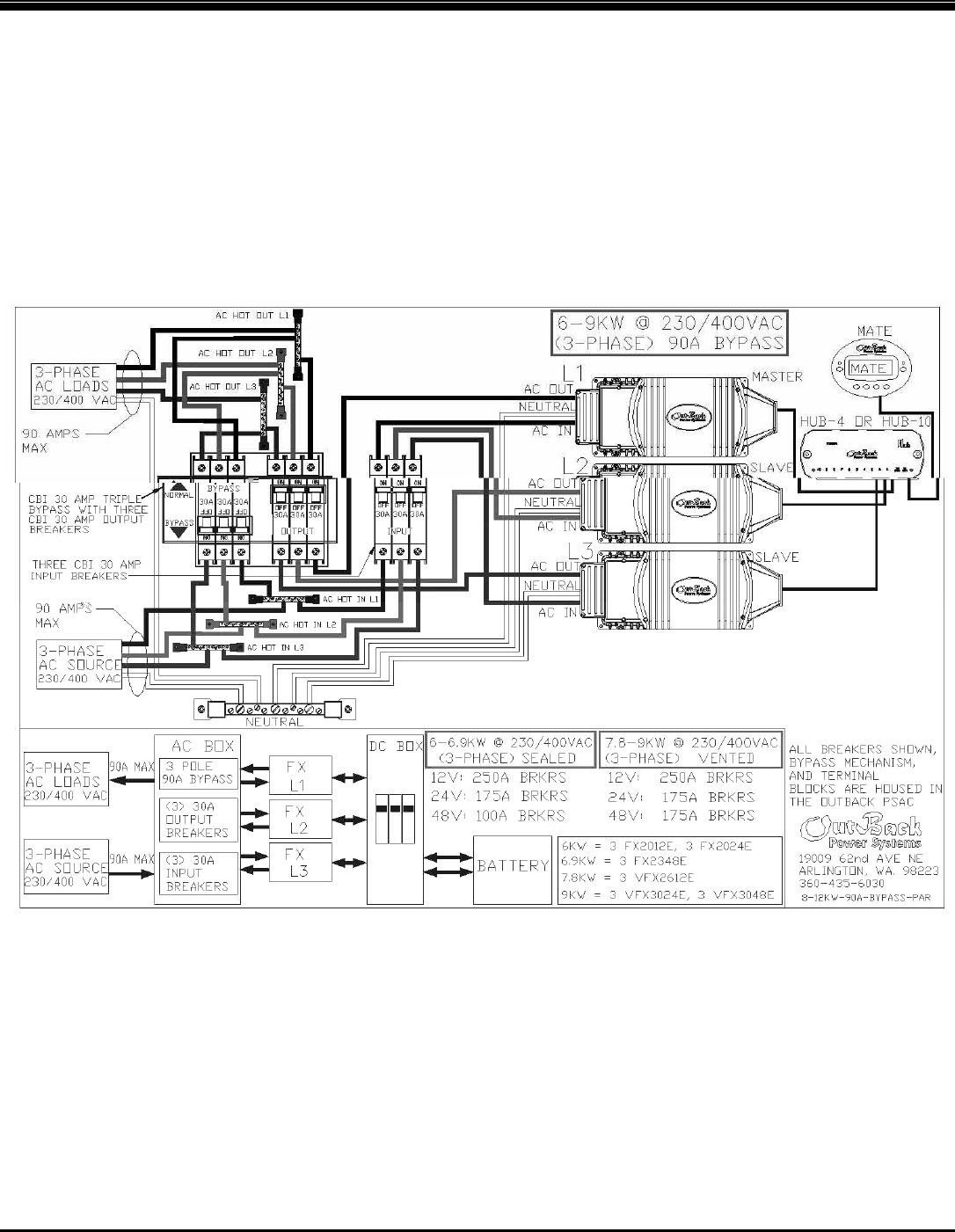
The following diagram illustrates a typical 3-phase FX installation using three FX’s. This system will produce 230VAC per phase and
400VAC from phase to phase. At this time there can only be one FX per phase on a 3-phase system. For this type of installation, use
of OutBack Power Systems PS-3PH system is recommended. This FX system will require six OBDC-30 CBI breakers for the AC input
and AC output and one OBDC-30T CBI breaker for the AC bypass. Additional breakers can be purchased and installed in the PSAC if
necessary. The AC wiring from the AC source and to the AC loads must handle 30 amps AC or more. All other AC wiring must handle
a capacity of 30 amps AC or more. This type of FX system can continuously power 6-9KW of loads depending on which model is used.
Connecting more power than the continuous rating of the FX may cause breakers to trip or the FX to shut off its AC output. A HUB and
a MATE must be connected to stack these FX’s in 3-phase. A MATE (through the HUB if one is needed) must be connected to adjust
any parameters or to display any meters. Once the FX has been programmed using the MATE, the MATE can be disconnected. The
programming will be saved within the FX’s non-volatile memory even if the FX is completely shut down.
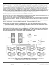
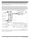
Three OutBack FX’s can be stacked in a 3-phase configuration to power loads that require 3-phase power. The diagram below
represents 3-phase stacking of three FX’s.
Program the top FX as Master (3PH MASTER) and the two lower FX’s as 3-phase Slaves (3PH SLAVE)
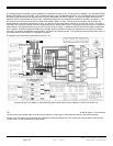
NOTES:
The AC OUTPUT NEUTRAL IS NOT BONDED TO THE CHASSIS OR THE GROUND TERMINAL of the FX system. This connection
is to be made by the installer either in the AC service entrance or within the AC load distribution panel of the electrical system.
The AC input, AC output and DC terminals are isolated from the metal chassis of the FX. Proper grounding of these circuits and the
chassis of the FX is the responsibility of the installer.