


Installation & Programming Manual FX & VFX “E” Series Inverte r/Charge r Sy ste m Copyright 2003 OutBack Power Systems, Inc.
19009 62
nd
Ave NE, Arlington WA 98223 USA
Page 12 Rev 7.0 07/02/04 Tel 360 435 6030 Fax 360 435 6019
AC WIRING CONNECTIONS
The FX system and the other OutBack balance of system components are designed to make it easy to meet any local and national
electrical installation requirements. When used outside of the USA, follow the local installation codes for your country.
If you are not familiar with the local installation codes, you should have the equipment installed by a qualified renewable energy
equipment dealer or electrician. All wiring methods are to be made in accordance with the local electric code.
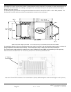
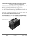
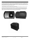
The FX includes an AC wiring compartment with both a removable cover and AC conduit plate. Depending on the type of installation,
the AC conduit plate may or may not be used.
The AC terminal block in the AC wiring compartment is designed to accept up to 6 AWG (13.3mm
2
) wires. A typical installation will use
8 AWG (8.35mm
2
) THHN type wire. 8 AWG (8.35mm
2
) is required in order to handle the “Export” model’s maximum input current of 30
amps. All AC wiring connected to the AC terminal block must be rated for at least 75˚ C. Torque all of the set screws on the AC
terminal block to 30 inch-pounds (equivalent to 2.5 foot-pounds or 3.4 Nm).
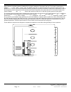
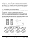
The AC input should be supplied to the FX through a 30 amp maximum AC branch rated circuit breaker. The AC hot input conductor
(black) should be connected to the AC HOT IN terminal. The AC neutral input conductor (white) may be connected to the AC
NEUTRAL IN terminal or a common Neutral bus. The AC NEUTRAL OUT terminal is common with the AC NEUTRAL IN terminal
within the FX and only one AC neutral connection is required to be connected to the FX if a separate AC neutral bus is installed.
The other three terminals of the AC terminal block are for AC output wiring. The AC HOT OUT terminal is to be connected to the AC
loads through branch rated AC circuit breakers.
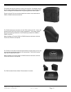
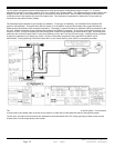
Many installations will use the OutBack AC-IOB-30 input/output bypass breaker assembly mounted in the OutBack PSAC or PS2AC.
This bypass assembly allows the user to completely bypass the FX. While in the bypass mode, AC current flows directly from the AC
source (generator or grid) through the bypass breaker and out to the loads. In addition to the AC bypass switch, Outback has separate
AC input breakers. These also need to be turned off. After the FX has been powered down through the DC breaker, the FX can then
be removed for servicing or replacement without loss of AC power to the AC loads of the system.
The AC terminal block includes two terminals labeled CHASSIS GROUND (older FX’s have on of these terminals labeled “Filter
Ground” even though it was never actually filtered). These terminals are connected to each other within the FX. Therefore, it is
necessary to connect only one of these terminals to ground. It should be noted that the grounding lug near the battery terminals may
also be connected to ground.
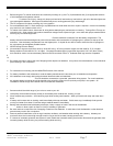
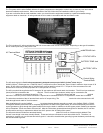
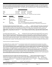
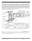
AC Terminal Block
Control Wiring
Terminal Block
MATE/HUB Jack
“STATUS” LED’s
BATTERY TEMP Jack
“BATTERY” LED’s