


Installation & Programming Manual FX & VFX “E” Series Inverte r/Charge r Sy ste m Copyright 2003 OutBack Power Systems, Inc.
19009 62
nd
Ave NE, Arlington WA 98223 USA
Page 54 Rev 7.0 07/02/04 Tel 360 435 6030 Fax 360 435 6019
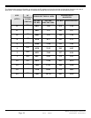
WIRE SIZES
The following chart contains information on wire sizes, the DC resistance of the wires and the corresponding diameters and areas of
these wires. This information can be used to calculate the voltage drop of the wires or to find an equivalent wire size.
CROSS-SECTIONAL AREA
APPROXIMATE
DIAMETER
SIZE
(AWG)
DC
Resistance
in Ohms
(1000 feet)
SQUARE
INCHES
SQUARE
MILLIMETERS
INCHES MILLIMETERS
14
3.14
.0032 2.08 .078 1.98
12
1.98
.0051 3.31 .101 2.57
10
1.24
.0082 5.26 .126 3.20
8
0.78
.0130 8.37 .162 4.11
6
0.50
.0206 13.30 .215 5.46
4
0.31
.0328 21.15 .269 6.83
2
0.19
.0521 33.62 .337 8.56
1
0.15
.0657 42.41 .376 9.55
1/0
0.12
.0829 53.50 .423 10.74
2/0
0.10
.1045 67.43 .508 12.90
3/0
0.08
.1318 85.01 .576 14.63
4/0
0.06
.1662 107.20 .645 16.38