IPLink Series High Speed Routers overview 20
Models 2603, 2621, and 2635 Getting Started Guide 1 • General Information
• Logging via SYSLOG, and VT-100 console. Console port set at 9600 bps 8/N/1 settings no flow control.
Security
• Packet filtering firewall for controlled access to and from LAN/WAN. Support for 255 rules in 32 filter sets.
16 individual connection profiles.
• DoS Detection/protection. Intrusion detection, Logging of session, blocking and intrusion events and Real-
Time alerts. Logging or SMTP on event.
• Password protected system management with a username/password for console and virtual terminal. Sepa-
rate user selectable passwords for SNMP RO/RW strings.
• Access list determining up to 5 hosts/networks which are allowed to access management system SNMP/
HTTP/TELNET.
• Logging or SMTP on events: POST, POST errors, PPP/DHCP, IP.
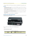
Front Panel Status LEDs and Console Port
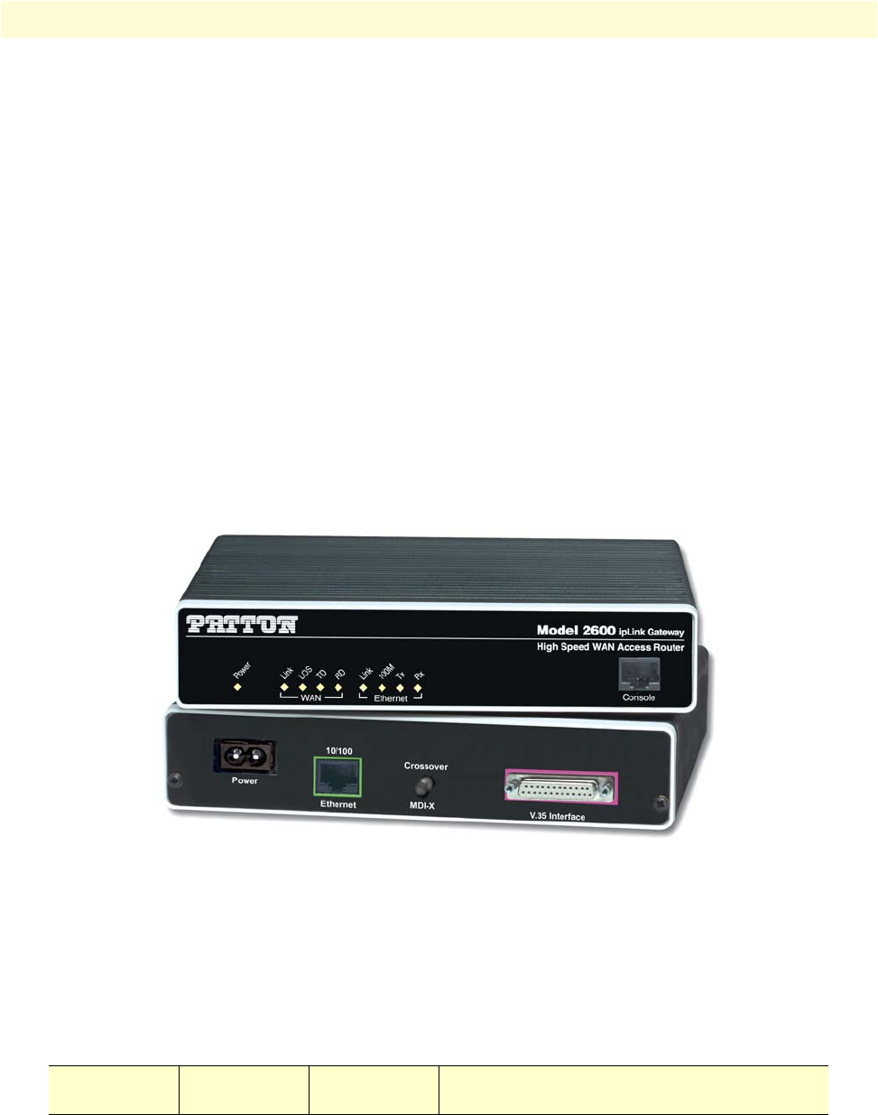
The IPLink routers have all status LEDs and console port on the front panel of the unit, and all other electrical
connections are located on the rear panel.
Figure 1. IPLink Series Router (Model 2635 shown)
The status LEDs from left to right are (see table 2 for LED descriptions):
• Power
• Sync Serial TD, RD, CTS, and DTR
• Ethernet Link, 100M, Tx, and Rx
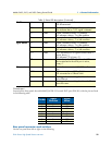
Table 2. Status LED descriptions
Power Green ON indicates that power is applied. Off indi-
cates that no power is applied.


