


44 Pelco Manual C573M-D (11/03)
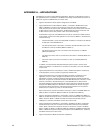
APPENDIX A – APPLICATIONS
The MDA can be used in several different applications. Note that, as illustrated in some of
the applications below, a maximum of 16 MDAs can be daisy-chained. When more than 16
MDAs are required, a CM9760-CDU-T must be used.
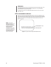
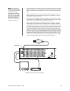
• Figure 37 illustrates a simple system configuration of the MDA.
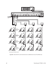
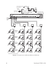
• Figure 38 illustrates a master MDA unit, MDA 1, connected to 63 MDA slave units:
MDA 2 to MDA 64. The slave units accept the master time and date from MDA 1,
which functions as the master clock. (An MDA functions as the master clock when unit
ID DIP switch 8 is set to the ON position. An MDA functions in slave mode when unit
ID DIP switch 8 is in the OFF position, which is the default setting.)
As illustrated in Figure 38, the CM9760-CDU-T must be used when an MDA functions
as the master clock time and date generator for more than 16 MDAs. In the illustration,
note the following:
– The RS-422 COM 1 port of the master MDA unit (MDA 1) connects to the RS-422
IN data port of the CM9760-CDU-T.
– The first RS-422 output of the CDU-T connects to the RS-422 COM 1 port of the
first MDA in a chain of 16 MDAs (MDA 2 to MDA 17).
– The second output of the CDU-T connects to the second chain of 16 MDAs
(MDA 18 to MDA 33).
– The third output of the CDU-T connects to the third chain of 16 MDAs (MDA 34 to
MDA 49).
– The fourth output of the CDU-T connects to a chain of 15 MDAs (MDA 50 to
MDA 64).
In addition, note that RS-422 shielded twisted pair cable is used to connect each
output of the CDU-T to a wall block for connection to the COM 1 port of the first MDA
in each chain.
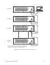
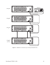
• Figure 39 illustrates a PC connected to a chain of 16 MDA units (MDA 1 to MDA 16).
In this application, the PC is used to program the 16 MDA units.
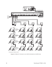
• Figure 40 illustrates a PC connected to 64 MDA units: MDA 1 to MDA 64. In this
application, the PC is used to program the 64 MDA units. The Pelco PV130
RS-232/422 converter provides an electrical interface between RS-232 and RS-422
data ports. In Figure 40, the PV130 interfaces the DB9 RS-232 port of the PC to a wall
block for connection to the RS-422 IN port of the CM9760-CDU-T. (Note that the
PV130 RS-232/422 converter eliminates the need to change the internal DIP switch
settings of the MDA COM port to RS-232 for communication with the PC.) A plug-in
power supply allows the PV130 to communicate serial port data over wire pairs for
distances up to 4,000 feet (1,219 m) on the RS-422 side.
Each of the first four outputs of the CDU-T connects to a chain of 16 MDAs (MDA 1 to
MDA 16, MDA 17 to MDA 32, MDA 33 to MDA 48, and MDA 49 to MDA 64).
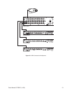
• Figure 41 illustrates a CM9760-CC1 connected to a chain of 16 MDA units (MDA 1 to
MDA 16). An RS-422 output of the CC1 connects to the RS-422 COM 1 port of the first
MDA in the chain. MDA 1 to MDA 16 accept the master time and date from the
CM9760-CC1; therefore, the MDAs must be set to slave mode.
• Figure 42 illustrates a CM9760-CC1 connected to 64 MDA units: MDA 1 to MDA 64.
An RS-422 output of the CC1 connects to the RS-422 IN data port of the CM9760-
CDU-T. Each of the first four outputs of the CDU-T connects to a chain of 16 MDAs
(MDA 1 to MDA 16, MDA 17 to MDA 32, MDA 33 to MDA 48, and MDA 49 to MDA 64).
MDA 1 to MDA 64 accept the master time and date from the CM9760-CC1; therefore,
the MDAs must be set to slave mode.
• Figure 43 illustrates an MDA connected to multiplexers.