


OPERATING INSTRUCTIONS
FOREWORD
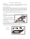
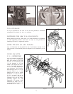
Porter-Cable Model 3807 is a high capacity 10" compound miter saw designed to cut wood and non-ferrous
metals. It can crosscut 11
1
… 2" x 3
3
… 16" and 9" x 3
7
… 8", miter at 45 both lef t and right 8
1
… 8" x 3
3
… 16", and 6
3
… 8" x
3
7
… 8", bevel at 45 lef t 11
1
… 2" x 2
3
… 16" and 8
1
… 2" x 2
5
… 8", compound 45 left miter and 45 bevel 8
1
… 8" x 2
3
… 16" and
6
1
… 2" x 2
5
… 8" and compound 45 right miter and bevel 8
1
… 8" x 1
7
… 8" and 3
1
… 2" x 2
5
… 8".
POWER CONNECTIONS
A separate electrical circuit should be used for your tools. If an extension cord is used, make sure the conductor
size is large enough to prevent excessive voltage drop which will cause loss of power and possible motor
damage. For distances up to 100 feet use #12 wire. For distances up to 150 feet use #10 wire. If an extension
cord is to be used outdoors it must be marked with the suffix W -A following the cord type designation. For
example SJTW-A to indicate it is acceptable for out door use. Replace damaged or worn cord immediately.
Before connecting the motor to the power line, make sure the switch is in the OFF position and be sure that
the electric current is of the same characteristics as st amped on motor nameplate.
CAUTION: Keep the extension cord away from the cutting area and position the cord so that it will not
be a tripping hazard or contact material being placed into or removed from the machine.
UNPACKING
1. Carefully remove the machine from the carton.
W e recommend you retain all p acking materials until
after you have inspected and satisfactorily operated
the machine.
W ARNING: Do not connect the machine to the
power source until you have read and
understood this entire instruction manual.
2. Place the machine on a firm, level surface where
there is plenty of room for handling and properly
supporting the workpiece.
3. Familiarize yourself with all features and controls
as explained in this manual.
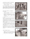
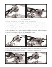
4. The machine is shipped with the cuttinghead
locked in the down position and the table rot ated to
the 45 degree right miter position, Fig. 2. To release
the head and move it to the operating position see MOVING CUTTINGHEAD TO THE UP POSITION and
MOVING THE TABLE TO THE 90 DEGREE CUT-OFF POSITION in this section.
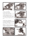
5. Unassembled items are shown in Fig. 3 for identification and use in assembling the saw.
1 Dust Elbow
2 W ork Clamp
3 Dust Bag
4 Open End Wrench
5
Fig. 2
Fig. 3
1
2
3
4