


8
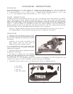
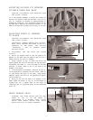
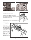
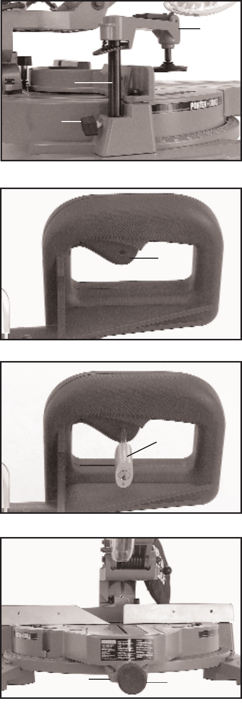
ASSEMBLING WORK CLAMP
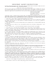
1. Insert post (A) Fig. 14, of work clamp assembly (B)
down through hole in the base of the machine as shown
and lock in place by tightening lock knob (C). The work
clamp (B) Fig. 14, can be used on the right or left side of
the cuttinghead.
2. For proper operation of the work clamp, refer to
section WORK CLAMPOPERATION.
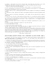
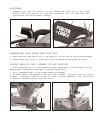
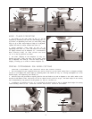
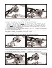
STARTING AND STOPPING MACHINE
To start the machine, depress switch trigger (A) Fig. 15.
To stop the machine, release the switch trigger.
This saw is equipped with an automatic electric blade
brake. As soon as the switch trigger (A) Fig. 15, is
released, the electric brake is activated and stops the
blade in seconds.
DANGER: A TURNING SAW BLADE CAN BE
DANGEROUS. AFTER COMPLETING CUT,
RELEASE SWITCH TRIGGER (A) FIG. 15, T O
ACTIVATE BLADE BRAKE. KEEP CUTTING-
HEAD DOWN UNTIL BLADE HAS COME TO A
COMPLETE STO P.
W ARNING: THE TORQUE DEVELOPED DURING
BRAKING MAY LOOSEN THE ARBOR SCREW.
THE ARBOR SCREW SHOULD BE CHECKED
PERIODICALLY AND TIGHTENED IF
NECESSARY.
LOCKING SWITCH IN THE OFF
POSITION
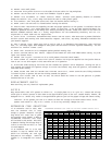
IMPORTANT: When the miter saw is not in use, the
switch should be locked in the OFF position using a
padlock (B) Fig. 16, with a
3
…16" diameter shackle to
prevent unauthorized use of the saw.
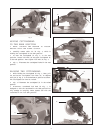
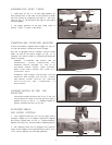
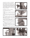
R O TATING TABLE
FOR MITER CUTTING
1. Your compound slide saw will cut any angle from a
straight 0 degree cut to 57 degrees right and 47 degrees
left. Rotate locking knob (A) Fig. 17, counterclockwise,
depress lock lever (B), and move table to desired position.
2. The compound miter saw is equipped with positive
stops at the 0 degree cut-of f position and at the 15, 22.5,
31.62, and 45 degrees left and right positions.
Fig. 15
A
Fig. 16
B
Fig. 17
B
A
Fig. 14
A
C
B