


9
ADJUSTING SLIDING FIT BETWEEN
M O VABLE TABLE AND BASE
CAUTION: DISCONNECT THE MACHINE FROM
THE POWER SOURCE.
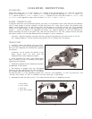
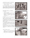
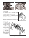
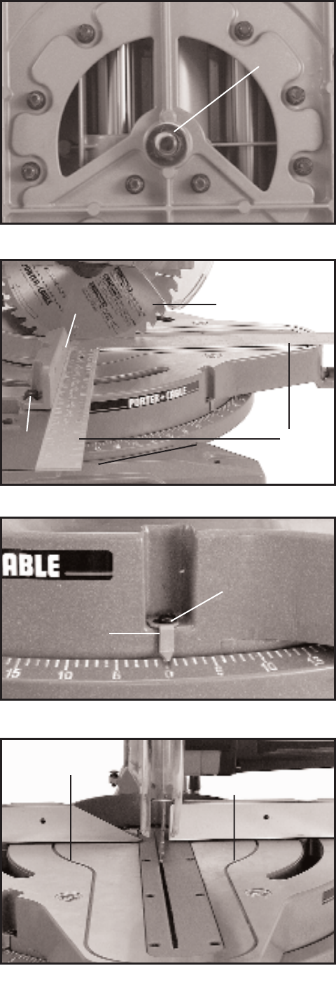
If it ever becomes necessary to adjust the sliding fit
between the movable table and the base, turn nut (A)
Fig. 18, clockwise to increase or counterclockwise to
decrease the sliding fit. This adjustment should not be
too tight that it restrict s the rot ating movement of the
table or too loose that it affects the accuracy of the saw.
ADJUSTING FENCE 90 DEGREES
TO BLADE
CAUTION: DISCONNECT THE MACHINE FROM
THE POWER SOURCE.
IMPORTANT: BEFORE MAKING THIS ADJUST-
MENT MAKE CERTAIN THE BLADE IS SET AT 0
DEGREES TO THE TABLE. SEE SECTION
ADJUSTING 0 AND 45 DEGREE BEVEL
POSITIVE STOPS.
1. DISCONNECT THE SAW FROM THE POWER
SOURCE.
2. Rotate the movable table so that the blade is 90
degrees to the fence and the positive stop for the 0
degree mark on the scale is engaged.
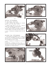
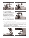
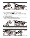
3. Using a square (A) Fig. 19, place one end of the
square against the front of the fence (B) and the other
end against the blade (C), with the blade in the down
position, as shown. Check to see if the fence is 90
degrees to the blade.
4. If an adjustment is necessary, the fence (B) Fig. 19,
can be adjusted by loosening the two screws, shown at
(D), that att ach the fence to the base, using wrench
supplied. Adjust the fence (B) as required and tighten
the two screws (D).
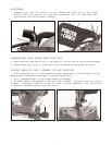
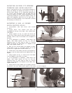
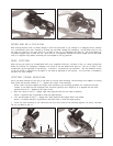
5.After you are sure the fence is 90 degrees to the
blade, adjust the cursor (F) Fig. 20, so the pointer is
aligned with the 0 degree mark on the scale by
loosening screw (G), adjusting cursor (F) and tightening
screw (G).
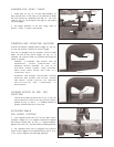
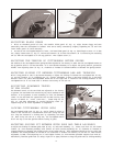
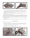
TABLE HAZARD AREA
W ARNING: THE AREA INSIDE THE TWO RED
LINES (A) FIG. 21, ON THE TABLE IS
DESIGNATED AS A HAZARD ZONE. NEVER
PLACE YOUR HANDS INSIDE THIS AREA
WHILE THE TO O L IS BEING OPERATED.
Fig. 18
A
Fig. 19
A
D
Fig. 20
G
B
C
F
Fig. 21
A
A