


11
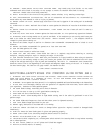
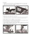
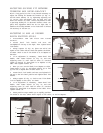
ADJUSTING SLIDING FIT BETWEEN
TRUNNION AND BEVEL BRACKET
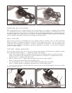
After a long period of time it may become necessary to
adjust the sliding fit between the trunnion (A) Fig. 27,
and the bevel bracket (B) by tightening adjusting nut
(C). NOTE: This adjustment must be made with the
bevel lock handle (D) loose. Correct adjustment is when
a good snug sliding fit is obt ained between these two
parts. This adjustment should not be too tight that it
restrict s the sliding movement or too loose that it af fects
the accuracy of the saw cut.
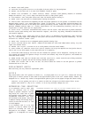
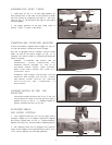
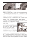
ADJUSTING 90 AND 45 DEGREE
BEVEL POSITIVE STO P S
1. DISCONNECT THE SAW FROM THE POWER
SOURCE.
2. Loosen bevel lock handle and move the
cuttinghead all the way to the right. Then tighten bevel
lock handle.
3. Using a square (A) Fig. 28, place one end of the
square on the table and the other end against the blade,
as shown. Check to see if the blade is at 90 degrees to
the table.
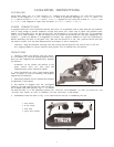
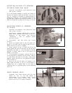
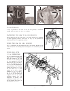
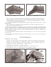
4. If an adjustment is necessary, loosen bevel lock
handle. Then loosen locknut (B) Fig. 29, and turn
adjusting screw (C) until head of screw (C) contacts
inside of casting (D) when blade is 90 degrees to the
table. Then tighten locknut (B).
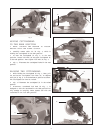
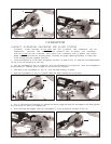
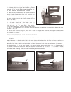
5. When you are certain blade is 90 degrees to table,
loosen screw (J) Fig. 30, and adjust pointer (H) to line
up with the 0 degree mark on bevel scale (K).
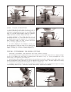
6. Loosen bevel lock handle and move cuttinghead all
the way to the lef t bevel position and tighten bevel lock
handle.
7. Using a square (A) Fig. 31, check to see if the blade
is at 45 degrees to the t able, as shown.
8. If an adjustment is necessary, loosen bevel lock
handle. Then loosen locknut (E) Fig. 29, and turn
adjusting screw (F) until head of screw (F) contacts
surface (G) when blade is 45 degrees to the table. Then
tighten locknut (E).
9. These positive stops enable you to rapidly position
the blade at the most common bevel angles to the table, 90 and 45 degrees.
Fig. 27
C
B
D
A
Fig. 28
A
Fig. 29
E
D
G
C
B
F
Fig. 30
H
Fig. 31
A
J
K