


14
5. Remove guide setting gauge from trimmer and install flush trimming bit.
6. Adjust depth of cut so that the straight portion of the bit extends below
the trimmer base at least the thickness of the material to be trimmed.
7. Make a trial cut on scrap material. Readjust if necessary.
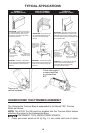
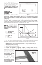
BEVEL TRIMMING
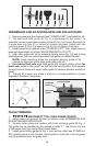
1. Follow Steps 1 through 5 under FLUSH TRIMMING, except install bevel
trimming guide (C) Fig. 4. This guide is identified by the letter “B” molded
onto it.
2. Adjust depth of cut so that only the bevel portion of the bit extends
below trimmer base at least the thickness of the material to be trimmed.
3. Make a trial cut on scrap material to check alignment. Readjust if
necessary.
USING STRAIGHT EDGE GUIDE
The straight edge guide (D) Fig. 4, maybe used with either bit for trimming
straight edges.
Assemble it to the guide base and adjust similar to the other guides.
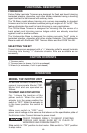
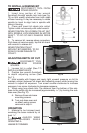
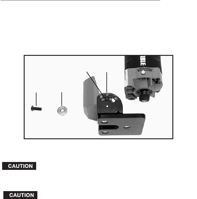
MODEL 7319 TILT BASE TRIMMER ASSEMBLY
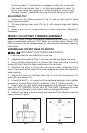
Model 7319 Tilt Base Trimmer is completely assembled at the factory. The
base is assembled or removed from Model 7301 motor with base locking
screw (A) Fig. 6.
NOTE: There is a flat washer (B) Fig. 6, on the locking screw.
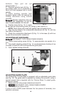
Model 7319 Tilt Base is designed for use with 43216PC flush trim bit
for trimming into corners. It may also be used with other “self pilot”
trim bits for conventional trimming at 90° setting.
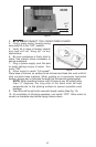
ADJUSTING DEPTH OF CUT
DISCONNECT TOOL FROM POWER SOURCE.
Loosen base locking screw and move motor unit up or down to
decrease or increase depth of cut.
It may be necessary with some bits to withdraw bit from
collet to obtain maximum depth of cut. When doing this
Fig. 6
C
D
B
A