


19
bottoms. Then pull bit out
approximately
1
/8
".
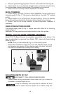
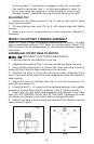
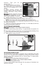
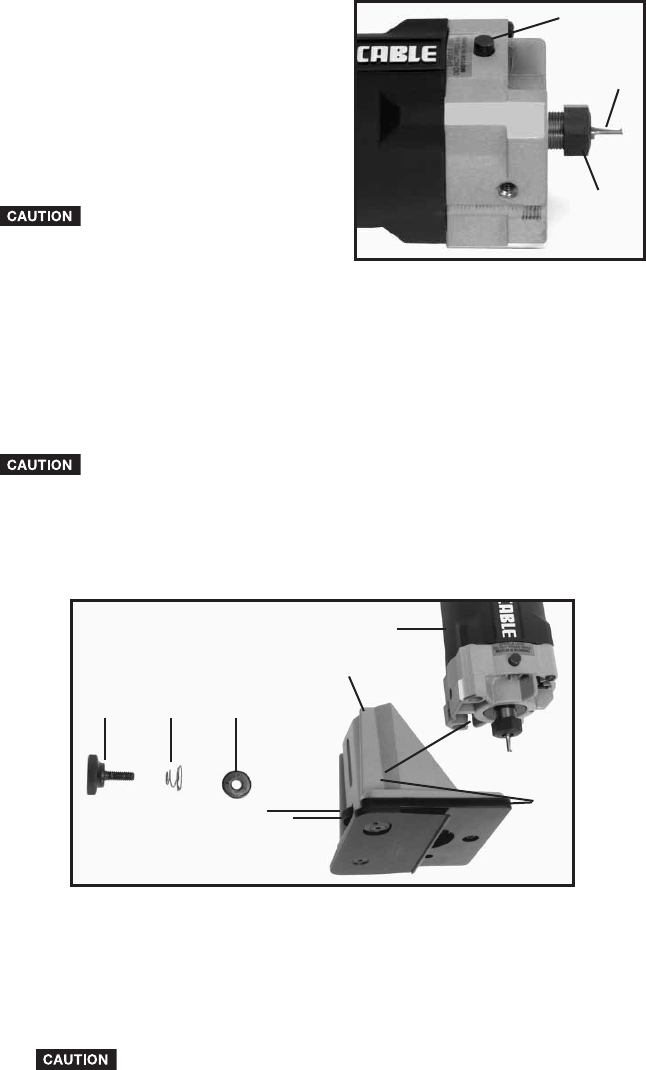
2. Depress spindle lock (B) Fig. 14,
and rotate collet nut (C) clockwise by
hand until lock engages hole in motor
spindle.
3. While holding spindle lock
engaged, tighten collet nut securely by
turning clockwise using wrench
provided.
NEVER TIGHTEN COLLET
WITHOUT BIT INSERTED, TO DO SO
MAY CAUSE DAMAGE TO COLLET.
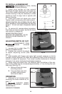
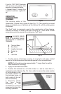
4. Position base (A) Fig. 15, to motor
(B) and secure using locking screw (E), spring (D) and washer (C).
NOTE: Orient spring with small end against head of locking screw.
5. Align the two holes in the undersciribe attachment (G) Fig. 15, with the
two holes in the base (A).
6. Attach the underscribe attachment (G) Fig. 15, to the base (A) with two
screws (H) and eccentric washer (J).
ADJUSTING BIT EXPOSURE
DISCONNECT TOOL FROM POWER SOURCE.
1. Loosen base locking screw (E) Fig. 15, approximately one-quarter of a
turn.
2. Turn depth adjusting wheel (F) Fig. 15, counterclockwise (looking at top
of wheel) to lower bit until it just touches the guide plate.
3. Firmly tighten locking screw (E).
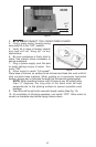
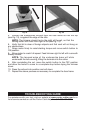
ADJUSTING GUIDE PLATE
The Underscribe Trimmer Base is equipped with an adjustable guide plate
(see Fig. 16). The guide plate is adjusted by rotating the eccentric, using a
special wrench that is supplied with the Trimmer Base. To adjust guide,
proceed as follows:
1. Make a trial cut using scrap material and check fit.
2. DISCONNECT TOOL FROM POWER SOURCE.
3. Turn eccentric to correct fit-up:
If joint is TOO LOOSE (crack between the two pieces of laminate), turn
eccentric clockwise.
Fig. 14
A
B
C
Fig. 15
A
B
CDE
F
G
H
J