


12
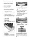
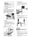
8. With assistance, raise bed and leg assembly
right-side up.
Bed and leg assembly is
heavy. Use care when lifting.
9. Rotate the leveling feet as needed to establish
level for the lathe.
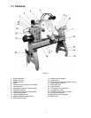
10. Install headstock, toolrest base and tailstock,
and both stop bolts (B, Figure 3).
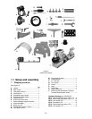
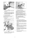
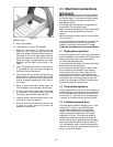
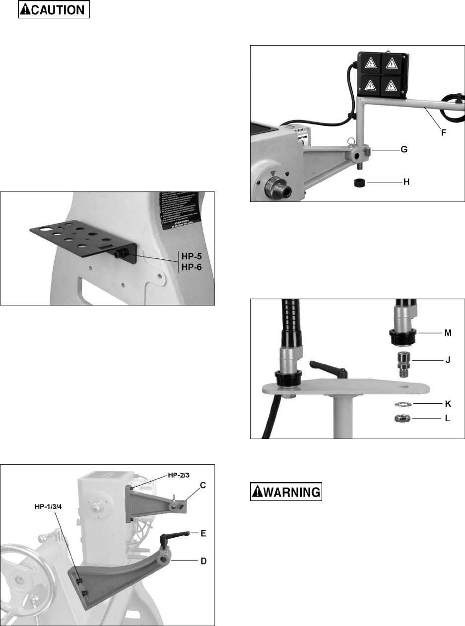
7.5 Tool caddy
Install tool caddy (Figure 7) to either end of lathe
with two screws and washers (HP-5/6). The left
end, near the headstock, is generally preferred.
The tool caddy has holes for placing knockout rod,
centers, faceplate wrench, air adaptors, etc.
Accessories can also be stored in the tailstock
cavity.
Figure 7
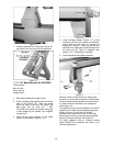
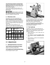
7.6 Brackets
1. Install guard bracket (C, Figure 8) with two
screws and lock washers (HP-2/3).
2. Install comparator bracket (D, Figure 8) to
tailstock with fasteners (HP-1/3/4). The bracket
holes are slotted for alignment with guard
bracket.
3. Install locking handle (E, Figure 8).
See section 9.11, “Comparator” for further
information.
Figure 8
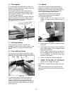
7.7 Lamp holder set
1. Install shaft of lamp holder (F, Figure 9) into
guard bracket hole, and tighten handle (G).
2. Install collar (H) beneath and tighten set screw
on collar.
Figure 9
To install lamps:
3. Insert stud (J, Figure 10) into plate and secure
with lock washer and nut (K/L).
4. Lift up collar (M) on lamp arm while pushing
arm down completely onto stud. Push collar
back down to secure.
Figure 10
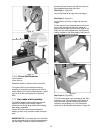
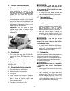
7.8 Guard
The guard must always be
used in operations that will allow its use.
See Figure 11.
1. Loosen set screw of outer collar (N) and
remove collar.
2. Insert guard support rod into guard bracket
while lifting up on plunger (O). Release
plunger and it will snap into position as you
slide support rod farther in.
3. Reinstall collar (N) on end of guard support rod
and tighten set screw.