17
The inverter does not require any programming; it
has been pre-programmed from the factory. The
buttons on the face of the inverter should never
be pushed at any time. Use only the controls on
the front of the headstock.
If you suspect a problem with the inverter or its
settings, contact Powermatic technical service at 1-
800-274-6846.
A lightning strike or power surge
may cause the inverter to fail. When lathe is not in
use, disconnect power plug, or have a 3- or 4-pole
disconnect installed on the power side.
8.4 Extension cords
An extension cord is not recommended; try to
position equipment within reach of the power
source. If an extension cord becomes necessary,
be sure it is heavy enough to carry the current your
product will draw. An undersized cord will cause a
drop in line voltage resulting in loss of power and
overheating.
Table 1 shows recommended size to use
depending on cord length and nameplate ampere
rating. If in doubt, use the next heavier gauge. The
smaller the gauge number, the heavier the cord.
Ampere
Rating
Volts
Total length of
cord in feet
More
Than
Not
More
Than
120
240
25
50
50
100
100
200
150
300
AWG
00 06 18 16 16 14
06 10 18 16 14 12
10 12 16 16 14 12
12 16 14 12
Not
Recommended
Extension Cord Recommendations
Table 1
9.0 Adjustments
9.1 Headstock/tailstock movement
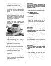
To slide headstock, loosen locking cams at rear
(see A, Figure 3) with provided wrench. Always
retighten cams before operating lathe.
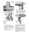
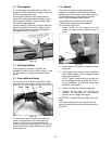
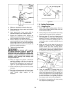
To slide tailstock, swing locking handle (B, Figure
23) to upright position. Push locking handle forward
or back to tighten tailstock in place.
Figure 23
To remove headstock, tailstock or toolrest base
from bed, unscrew and remove either of the stop
bolts (see B, Figure 3). After remounting these
items on the Lathe, reinstall stop bolt(s).
For most turning operations, except outboard
turning, the headstock should be positioned at left
end of bed, and only the tailstock moved to
accommodate the workpiece.
9.2 Cam tightness
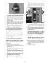
If headstock, tailstock or tool rest base does not
tighten properly against bed when locking handle is
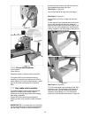
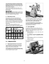
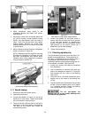
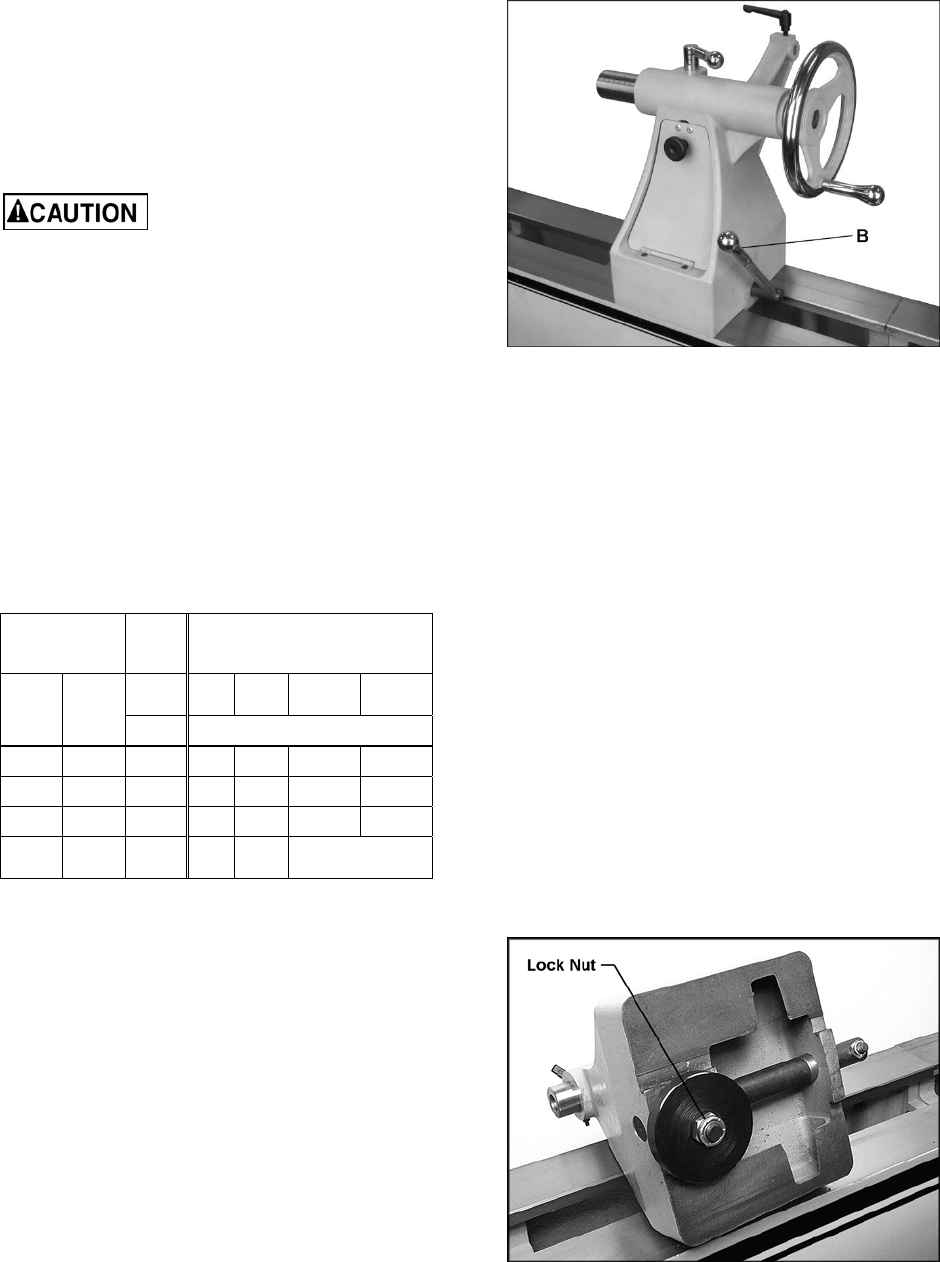
tightened, it may need adjusting. Figure 24 uses
tailstock as example:
1. Remove stop bolt on end of lathe bed, and
slide tailstock off.
2. Turn tailstock on its side, and slightly tighten
lock nut with a wrench. (Headstock has two
nuts.)
3. Mount tailstock on bed and verify adjustment.
Repeat as needed.
4. Reinstall stop bolt.
Figure 24


