


19
9.7 Centers: Installing/removing
1. Disconnect lathe from power source.
2. To install a spur center or live center (a spur
center should first be mounted to your
workpiece; see section 11.4), clean tapered
end of center and inside of headstock taper
spindle, then push center into headstock
spindle.
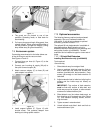
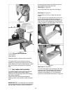
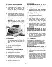
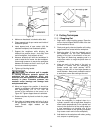
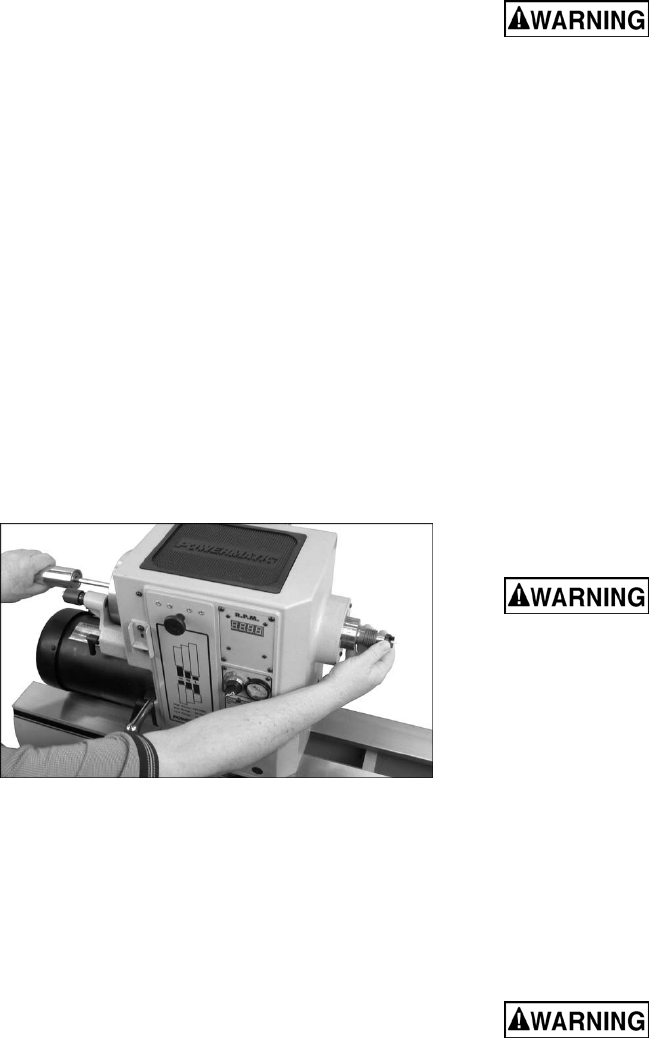
3. To remove a spur center or live center, first
remove workpiece from lathe. Insert knockout
rod (Figure 28) through hole in handwheel and
firmly tap the tapered end of spur center. The
sliding collar on the knockout rod helps give
the necessary impact without having to use a
mallet against the end of the rod.
IMPORTANT: Hold the center by either
placing your thumb and forefinger on outside
diameter of spur center, or wrapping center
with a rag. The center can be damaged if
allowed to fall.
Figure 28
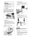
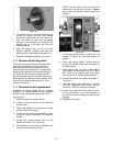
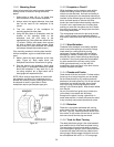
9.8 Spindle lock
1. Push spindle lock button (see G, Figure 33),
and rotate spindle slightly until button goes
entirely into recess. Slide plate down over
button.
2. Rotate spindle by hand until it locks.
3. Slide plate upward to release spindle.
IMPORTANT: Always release spindle lock before
turning on lathe.
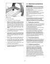
9.9 Face plate: Installing/removing
1. Disconnect lathe from power source.
2. Mount face plate to your bowl blank.
3. Lock spindle.
4. Install face plate onto threads of headstock
spindle and rotate clockwise hand-tight. When
lathe is turned on (forward rotation), the
rotational force will snug the face plate even
farther onto the threads.
5. Face plate is now ready for turning.
If at any time you will be
reversing spindle rotation, make sure the two
set screws in the face plate are tight! Failure to
do this may cause the face plate to loosen from
the headstock spindle.
6. To remove face plate, loosen the two set
screws. Engage spindle lock, and turn face
plate counterclockwise with face plate wrench.
9.10 Vacuum chuck:
Installing/removing
1. Disconnect lathe from power source.
2. Lock spindle.
3. Install vacuum chuck onto threads of
headstock spindle and rotate clockwise hand-
tight. When lathe is turned on (forward
rotation), the rotational force will snug the
vacuum chuck even further onto the threads.
4. Make sure vacuum adaptor is inserted into
handwheel, and air supply is connected. Turn
on air system and place workpiece against
vacuum chuck.
If at any time you will be
reversing spindle rotation, make sure the set
screws in the vacuum chuck are tight! Failure
to do this may cause vacuum chuck to loosen
from headstock spindle.
5. To remove vacuum chuck, turn off air supply,
and loosen the two set screws. Engage
spindle lock, and turn vacuum chuck counter-
clockwise with face plate wrench.
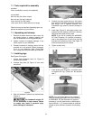
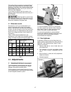
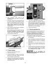
9.11 Comparator
The spindle comparator consists of two comparator
centers inserted into the brackets at rear of lathe.
The comparator is used to mount a finished, or
“reference” spindle, from which measurements can
be taken, the measurements being transferred to
the new piece being turned.
Guard must be removed to
use spindle comparator. Use caution and wear
a face mask when turning without guard
installed.
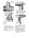
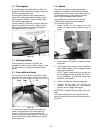
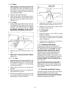
1. Remove guard from bracket and swing lamp
holder away.
2. Install comparator spur center into guard
bracket, by lifting up on plunger and inserting
comparator spur center until its point is about
even with the point of the spur center in the
headstock spindle. See Figure 29. The plunger
in the bracket should engage one of the holes
in the comparator center at this position.