


21
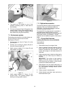
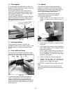
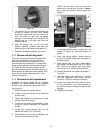
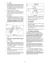
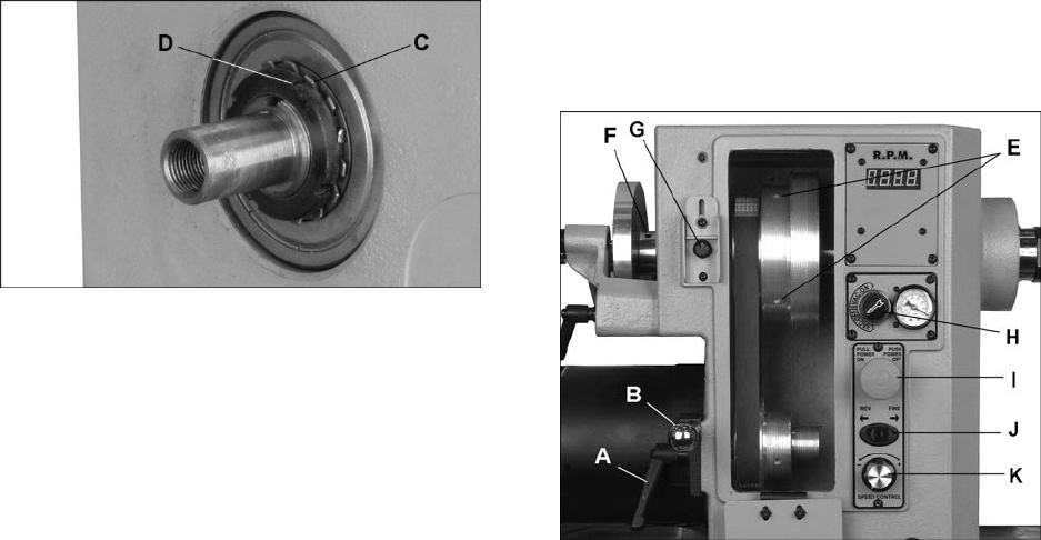
Figure 32
5. The bearing lock nut should be tightened just
enough to remove end play, and spindle
should still rotate freely. Run the lathe for a
time, and check for heat from the spindle
bearings. If the bearings are running hot, the
bearing lock nut is too tight and should be
loosened slightly.
6. After the bearing lock nut (D) has been
properly adjusted, carefully bend back into
place any tabs on the tabbed lock washer (C).
7. Reinstall handwheel and tighten set screws.
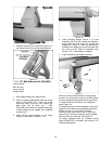
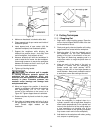
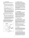
9.14 Sheave and belt alignment
The motor and spindle sheaves are aligned with
each other at the factory, but if any service is
performed that affects their alignment it is very
important that they be realigned. To realign them,
loosen the two set screws on the spindle sheave
(E, Figure 33) with a hex key, and slide spindle
sheave into proper position. Re-tighten set screws.
When sheaves and belt are properly aligned, there
should be no unusual pulsing sounds or noise
coming from the belt.
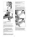
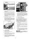
9.15 Sheave/drive belt replacement
Replacing the spindle sheave can be a difficult
procedure; it is recommended that the headstock
be taken to an authorized service center for this.
See Figure 33.
1. Disconnect lathe from power source.
2. Loosen lock handle (A) and lift up handle (B)
to raise motor.
3. Tighten lock handle (A) to hold motor in raised
position. Slip belt off pulleys.
4. Loosen two set screws on handwheel (F) with
a hex key, and pull handwheel off headstock
spindle.
5. Loosen and remove bearing lock nut and
tabbed lock washer (C/D, Figure 32).
6. Slide spindle a short way out of headstock, just
enough to remove sheave or belt.
NOTE: You may have to tap the end of the
spindle with a wood block to move it. (Never
use a steel face hammer directly against the
spindle.)
Figure 33
7. If replacing spindle sheave, loosen two set
screws (E, Figure 33), and slide sheave off
spindle.
8. Install new spindle sheave, loosely securing
the two set screws. Make sure the sheave is
oriented properly.
9. Slide spindle back into place, install tabbed
lock washer, and bearing lock nut (C/D, Figure
32). Check for any spindle play at this point
(See section 9.13, “Checking Spindle Play”).
10. Reinstall handwheel and tighten set screws (F,
Figure 33).
11. Align new sheave (see section 9.14, “Sheave
and Belt Alignment”) then tighten two set
screws (E, Figure 33) securely on sheave.
12. Loosen lock handle and allow motor to lower.
Do not overtension; a very light pressure on
the tension handle is adequate to prevent belt
slippage.
13. Retighten lock handle.