


17
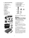
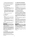
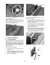
9.4.3 Extension plate
The extension plate (D, Figure 17) can be adjusted
by sliding to the right or left or removed entirely.
To adjust, loosen two lock handles (E), slide the
extension plate and retighten lock handles. Make
sure end of extension plate is not in blade path.
NOTE: The lock handles (E) are adjustable. Pull
out on handle, rotate it to different position, then
release, making sure it seats itself upon the pin.
To remove extension plate, slide it completely off
and remove lock handles (E) and mounting
hardware.
9.4.4 Calibration
1. Place miter gauge into one of the slots on the
table.
2. Set miter gauge at 90º to blade (0º setting on
the scale) by loosening lock handle (A), then
pulling out spring-loaded knob (C) and turning
body (B) until 0º is indicated on scale.
3. Measure accuracy of miter gauge against slot
with a combination square.
If adjustment is needed:
4. Adjust body (B) until it is square (90º) to miter
slot.
5. Tighten lock handle (A).
6. Verify that scale indicator (G) reads 0º. If
further adjustment is needed:
7. Loosen screw (F) and adjust indicator (G) until
it reads 0º.
8. Tighten screw (F).
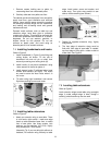
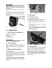
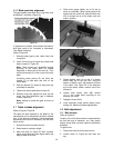
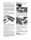
9. If the above procedure does not satisfactorily
align the miter gauge, loosen two screws (J,
Figure 18) beneath mounting block and shift
block as needed. Retighten screws when
finished.
Figure 18
NOTE: The bar of the miter gauge has two slots
with set screws (H, Figure 17). Adjust these set
screws (4mm hex key) to eliminate any play
between bar and miter slot.
9.5 Blade tilt stop adjustment
The stops for 90°, 45° blade tilt, and elevation
settings have all been factory set, and should
require no immediate adjustment. The settings
should be confirmed by the operator, however, and
especially if cuts become inaccurate. Both tilt stops
are located inside cabinet in front of the motor.
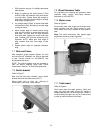
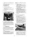
9.5.1 Tilt stop 90°
1. Disconnect machine from power source.
2. Make sure table insert has been leveled with
table surface. See section 7.11.
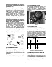
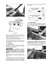
3. Raise blade all the way, and place a 90°
square on the table and against blade (Figure
19). Make sure that a blade tooth does not
obstruct the actual reading.
Figure 19
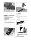
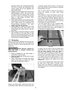
4. Tilt blade with handwheel until square and
blade are flush.
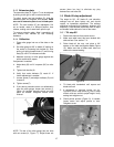
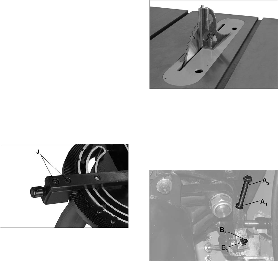
5. If adjustment is required, loosen nut (A
1
,
Figure 20) on 90° stop screw (A
2
) with a 12mm
wrench, and turn screw to proper height. Verify
setting and retighten nut.
6. Check pointer position (Figure 21). If needed,
loosen screw and adjust pointer to zero.
Retighten screw.
Figure 20