


11
electric current to reduce the risk of electric
shock to the operator.
Improper connection of the equipment-
grounding conductor can result in risk of electric
shock. The conductor, with insulation having an
outer surface that is green with or without yellow
stripes, is the equipment-grounding conductor. If
repair or replacement of the electric cord or plug
is necessary, do not connect the equipment-
grounding conductor to a live terminal.
Check with a qualified electrician or service
personnel if the grounding instructions are not
completely understood, or if in doubt as to
whether the tool is properly grounded.
The sander should be connected to a dedicated
circuit with a minimum 100 Amp service. The
sander has been factory wired to run at 230 volt
operation. It can be converted to 460 volt if
desired. See the appropriate sections below.
8.2 230 Volt Operation
The sander may be fitted with a 230 volt plug, or
may be “hard-wired” directly to an electrical
control panel. If hard-wired to a panel, make
sure a disconnect is available for the
operator.
Refer to the diagram inside the sander’s
electrical box for clarification of electrical
connections. These diagrams are also shown in
sections 17.0 and 18.0 of this manual.
1. Make sure the machine’s plug is
disconnected from the power source. If it will
be hard-wired, make sure the fuses have
been removed or the breakers have been
tripped in the circuit to which the sander will
be connected. Place a warning placard on
the fuse holder or circuit breaker to prevent
it being turned on while the machine is
being wired. Always follow proper Lock
Out/Tag Out procedures when performing
any wiring on this machine.
2. Make sure the power source corresponds to
the specifications of the sander as recorded
on the sander’s motor plate.
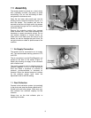
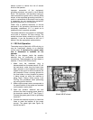
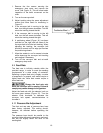
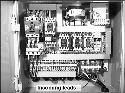
3. Open the sander’s electrical box and
connect the three incoming power leads to
the terminals marked R,S,T. See Figure 5.
Connect the green ground wire to grounding
terminal E.
4. Connect the machine to power (or install the
fuses or reset the breaker at the power
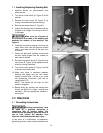
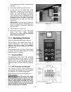
source). The power light (see Figure 19)
should now be lit.
Figure 5
(Model WB-25 shown)