


17
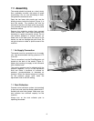
If the ends of the workpiece are sniped, the front
pressure bars are too low. The pressure should
be enough to firmly hold the workpiece against
the conveyor, but not so hard that the ends of
the workpiece spring up after clearing the bar.
Also, if the ends of the bars are not exerting
equal pressure, the workpiece will tend to move
sideways on the conveyor during sanding.
To raise or lower each set of pressure bars:
1. Disconnect sander from power source.
2. The sanding belt should be installed, and
the air valve turned ON.
3. Place a sanded panel with even thickness
on the conveyor table and under the
pressure bars. The panel should be long
enough to contact both front and back sets
of pressure bars.
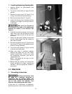
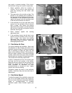
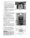
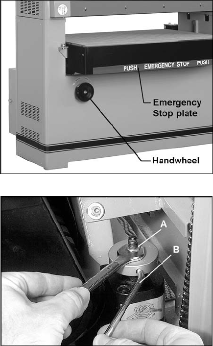
4. Raise the table manually using the
handwheel (Figure 16) until the panel
contacts the pressure bars.
5. Make sure the pressure at the right and left
side of pressure bars is even.
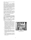
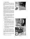
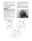
6. If adjustment is needed, release the lock nut
(A, Figure 17) with a 14mm wrench.
7. Insert the adjusting tool (B, Figure 17) into a
hole in the adjusting knob. Rotate the
adjusting knob clockwise to raise that side
of the pressure bar, counterclockwise to
lower it.
8. When finished, re-tighten lock nut (A, Figure
17).
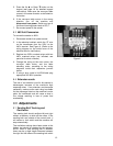
9.11 Table Parallelism
Parallelism of the conveyor table to the contact
roller has been factory-set and should not
require further adjustment. However, as the
machine receives extended use, this setting
should be checked.
Inspect parallelism by one of two methods:
1. Use a sanded board of equal thickness.
Pass the board several times through the
machine at a sanding depth of
approximately 1/64”, then measure the
thickness of the board at different points
along the edges with calipers. If excessive
variation occurs, the table needs adjusting.
OR, remove the sanding belt and place a
gauge of some kind at one side of the
conveyor table and below the contact roller.
Raise the table manually using the
handwheel until the gauge just touches the
contact roller. Repeat at the other side of
the table and compare the gauge readings.
Figure 16
Figure 17