


18
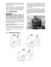
If the readings are different, the table needs
adjusting.
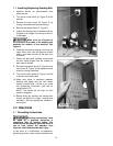
2. Disconnect sander from power source.
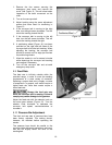
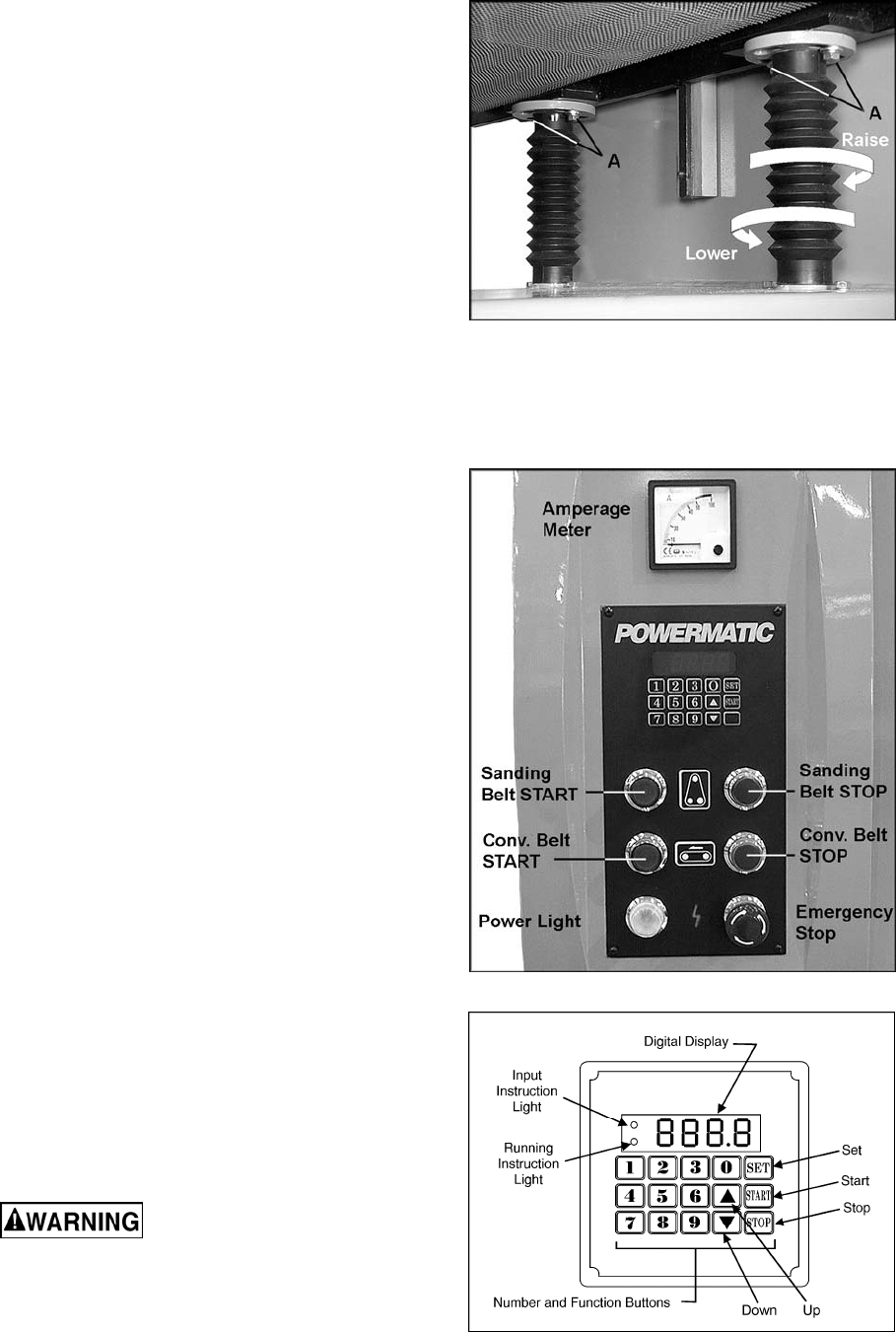
3. At the area of the table that needs
adjustment, loosen the two screws (A,
Figure 18) on the bracket of the elevation
screw, and rotate the bracket as needed.
(The elevation screw is protected by the
dust guard bellow.) Turn the elevating screw
clockwise to lower the table in that area,
counterclockwise to raise the table (see
Figure 18).
IMPORTANT: Turn both elevating screws at
one side of the table an equal amount, in
order to maintain front-to-back parallelism
with the rollers.
4. Tighten screws (A, Figure 18).
5. Re-connect sander to power, and make
further test runs. Make additional
adjustments as needed, with the machine
disconnected from power.
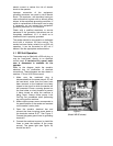
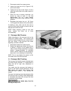
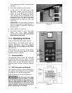
10.0 Operating Controls
Figure 19 shows the control panel functions.
The emergency stop button shuts down all
machine operations. The button remains
engaged after being pushed. To disengage,
rotate the ring until the emergency stop button
pops back out.
The emergency stop cover has a plate (shown
in Figure 16) which shuts down all machine
operations when it is pushed.
10.1 Amperage Meter
The amperage meter (Figure 19) continually
monitors the load upon the sander. To avoid
tripping of the circuit breaker and the overload
relays, reduce the load immediately when the
amperage meter indicates excessive amperage
pull.
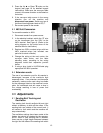
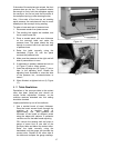
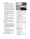
10.2 LED Controller and Keypad
The controller is used for precise positioning of
the conveyor table based upon the workpiece
thickness and your desired sanding depth.
Figure 20 shows the key features of the unit.
The LED control unit comes
pre-programmed from the factory. Do NOT
alter the specifications of your control unit
without authorization from WMH Tool Group.
Incorrect programming of the device could
cause unit failure as well as risk of injury to
people and damage to the sander.
Figure 18
Figure 19
Figure 20