


64
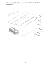
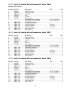
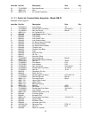
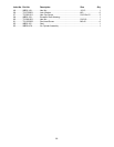
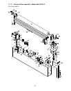
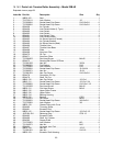
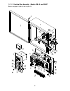
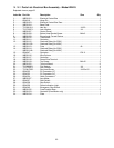
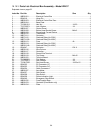
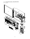
16.15.3 Parts List: Electrical Box Assembly – Model WB-37
Exploded view on page 62.
Index No. Part No. Description Size Qty
1 ............... WB25-801 ................Electrical Control Box ........................................................................... 1
2 ............... 6294516...................Hinge Pin .............................................................................................. 2
3 ............... WB25-803 ................Electrical Control Box Door .................................................................... 1
4 ............... WB25-804 ................Base Plate ............................................................................................. 1
5 ............... TS-0561011 .............Hex Nut ..............................................................1/4-20 ......................... 4
6 ............... TS-0720071 .............Lock Washer ......................................................1/4 .............................. 4
7 ............... WB25-807 ................Control Panel......................................................................................... 1
8 ............... WB25-808 ................Button Head Socket Screw .................................M4x8 .......................... 4
9 ............... WB25-809 ................Proportional Current Device ................................................................... 1
10 ............. W B25-810 ................Transformer ........................................................................................... 1
11 ............. W B37-811 ................Contactor .............................................................................................. 1
12 ............. W B37-812 ................Overload Relay (for 230V) ..................................................................... 1
................. WB37-812A .............Overload Relay (for 460V) ..................................................................... 1
13 ............. W B25-813 ................Fuse ...................................................................4A .............................. 2
14 ............. W B25-814 ................Overload Relay (for 230V) ..................................................................... 1
................. WB25-814A .............Overload Relay (for 460V) ..................................................................... 1
15 ............. 6294647...................Contactor ...........................................................CN-11......................... 3
16 ............. W B25-816 ................Wire Column ......................................................................................... 1
17 ............. W B25-817 ................Controller .............................................................................................. 1
18 ............. W B25-818 ................Power Wire Terminal ............................................................................. 1
19 ............. W B25-819 ................Tap Screw ..........................................................M4x10 ........................ 2
20 ............. W B25-820 ................Terminal Board ...................................................................................... 8
21 ............. TS-0680021 .............Flat Washer ........................................................1/4 .............................. 4
22 ............. TS-0720071 .............Lock Washer ......................................................1/4 .............................. 4
23 ............. TS-081F032 .............Pan H
ead Screw ................................................1/4-20x1/2 .................. 4
24 ............. 6294532...................PU Connector 1/2” ................................................................................. 4
25 ............. 6294533...................PU Connector 3/4” ................................................................................. 3
26 ............. 6294534...................Cable Connector 1” ............................................................................... 1
27 ............. W B25-827 ................Amp Meter............................................................................................. 1
28 ............. 6294537...................Start Switch ........................................................................................... 2
29 ............. 6294538...................Stop Switch ........................................................................................... 2
30 ............. 6294539...................Power Indication Light ........................................................................... 1
31 ............. 6294540...................Emergency Stop Switch ......................................................................... 1
32 ............. W B25-832 ................Fuse Support Base ................................................................................ 2
33 ............. W B25-833 ................Contactor (Feed Motor only) .................................................................. 1
34 ............. W B25-834 ................Plate ...................................................................................................... 1