


13
Repair or replace a damaged or worn cord
immediately.
The Lathe will operate on single phase or three
phase, 230 volt power supply. The Lathe should
be connected to a dedicated circuit. Make sure
the characteristics of your power supply match
the specifications on the motor plate of the
Lathe.
Single Phase Operation
A three wire pigtail for use on 230 volt single
phase power is attached to the inverter and may
be “hard-wired” to the power source, or
connected to a UL/CSA listed receptacle plug.
Connect the 230 volt supply to the black and
white leads and ground the green lead.
If you are hard-wiring the Lathe to a panel,
make sure a disconnect is available for the
operator. During hard-wiring of the Lathe, make
sure the fuses have been removed or the
breakers have been tripped in the circuit to
which the Lathe will be connected. Place a
warning placard on the fuse holder or circuit
breaker to prevent it being turned on while the
machine is being wired.
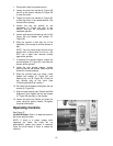
Three Phase Operation
If three phase power is used, it will be necessary
to replace the pigtail wire attached to the
inverter with a 12/4 wire and connect the three
hot leads to the inverter at R, S, T as shown in
the wiring diagram on page 40. Always connect
the ground lead.
Extension cords
If an extension cord is necessary, make sure the
cord rating is suitable for the amperage listed on
the machine’s motor plate. An undersized cord
will cause a drop in line voltage resulting in loss
of power and overheating.
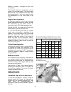
Use the chart in Figure 13 as a general guide in
choosing the correct size cord. If in doubt, use
the next heavier gauge. The smaller the gauge
number, the heavier the cord.
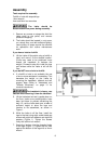
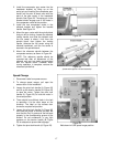
Adjustments
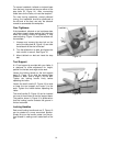
Headstock and Tailstock Movement
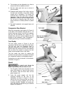
To slide the headstock or tailstock, swing the
locking handle (A, Figure 14) backward or
forward until the headstock/tailstock can slide
freely. When the headstock/tailstock is
positioned, rotate the locking handle to tighten it
securely.
Recommended Gauges (AWG) of Extension Cords
Extension Cord Length *
Amps
25
feet
50
feet
75
feet
100
feet
150
feet
200
feet
< 5 16 16 16 14 12 12
5 to 8 16 16 14 12 10 NR
8 to 12 14 14 12 10 NR NR
12 to 15 12 12 10 10 NR NR
15 to 20 10 10 10 NR NR NR
21 to 30 10 NR NR NR NR NR
*based on limiting the line voltage drop to 5V at 150% of the
rated amperes.
NR: Not Recommended.
Figure 13
Figure 14