19
1. Disconnect Lathe from power source.
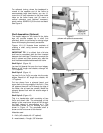
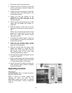
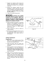
2. Loosen the pivot lock handle (A, Figure 25)
and lift up the tension handle (B, Figure 25)
to raise the motor.
3. Tighten the pivot lock handle (A, Figure 25)
to hold the motor in the raised position. Slip
the belt off the pulleys.
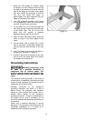
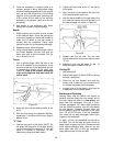
4. Loosen the two set screws on the
handwheel (A, Figure 26) with a hex
wrench, and pull the handwheel off the
headstock spindle.
5. Loosen and remove the bearing lock nut (B,
Figure 26) and tabbed lock washer (C,
Figure 26).
6. Slide the spindle a little way out of the
headstock, just enough to remove sheave or
belt.
NOTE: You may have to tap the end of the
spindle with a wood block to move it. (Do
NOT use a steel face hammer directly
against the spindle.)
7. If replacing the spindle sheave, loosen the
two set screws (C, Figure 25), and slide the
sheave off the spindle.
8. Install the new spindle sheave, loosely
securing the two set screws. Make sure the
sheave is oriented properly.
9. Slide the spindle back into place, install
tabbed lock washer (C, Figure 26), and
bearing lock nut (B, Figure 26). Check for
any spindle play at this point (See
“Checking Spindle Play” section).
10. Re-install the handwheel and tighten the set
screws (A, Figure 26).
11. Align the new sheave (see “Sheave and Belt
Alignment”) then tighten the two set screws
(C, Figure 26) securely on the sheave.
12. Loosen the pivot lock handle and lower the
motor using the tension handle. Re-tighten
the pivot lock handle.
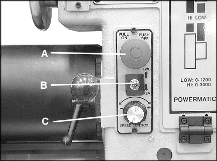
Operating Controls
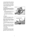
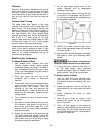
See Figure 27.
(A) On/Off Button: Push in to stop the machine;
pull out to start the Lathe.
NOTE: If there is a power outage while
operating the Lathe, the Lathe will not
automatically restart once power is restored.
Cycle the on/off switch in order to restart the
machine.
Figure 27


