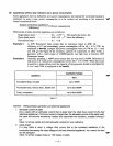
[Judgement
of
oil
level]
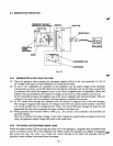
When sufficient oil is in the crankcase, both of inner and outer electrodes are immersed in the oil through
which current flows across the electrodes. The sensor judges that oil in the crankcase is sufficient.
4
When oil level goes down and the inner electrode is exposed to the air due to consumption of oil, no
current flow between the electrodes as air
is
considered to be electrically non-conductive.
The sensor in this case judges that oil
is
insufficient.
[Decision
of
oil
shortage]
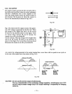
Oil level at the electrodes may go
down
momentarily probably due to the engine being slanted or affected
by vibration even if a sufficient oil is in the crankcase.
For that reason, the sensor has an electronic timer circuit to prevent it from interpreting as short of oil
when amount of oil is sufficient. The sensor has been designed
so
that the engine is to be stopped only
when oil-shortage
is
detected
for
5
seconds uninterrupted.
The timer employs an integration circuit and it is to be reset when the inner electrode is soaked in the oil
again before the sensor decides it as oil-shortage.
The
oil level where the sensor decides
as
oil-shortage, when oil level goes down gradually,
is
called
“threshold level”.
[Automatic stop
of
engine]
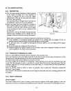
When
the
sensor decides as oil-shortage, it makes the engine to stop running automatically for protection
of engine.
Once the stopping circuit is activated, it keeps functioning until it confirms that the engine has made a
complete stop, then the circuit stops functioning automatically.
e
5-5-4
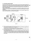
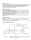
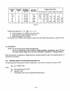
BLOCK
DIAGRAM
OF THE
CIRCUIT
Power circuit
Igniter
LED
indicator
Detection
Inner pole
-
Deley circuit
-
Stopping
circuit
circuit
oil
I
Outer
pole
Engine ground
Fig.
5-1
1
0
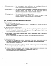
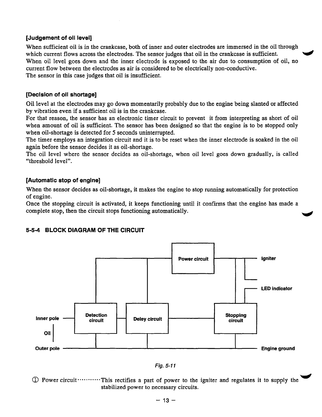
Power circuit----*-*---- This rectifies a part of power to the igniter and regulates it to supply the
-1
stabilized power
to
necessary circuits.
-
13-


