


Page 31
+
-
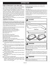
WARNING:
Before performing any adjustment, make sure the tool is
unplugged from the power supply and the switch is in the
off ( ) position. Failure to head this warning could result
in serious personal injury.
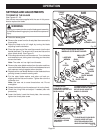
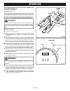
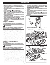
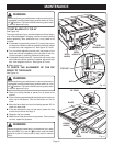
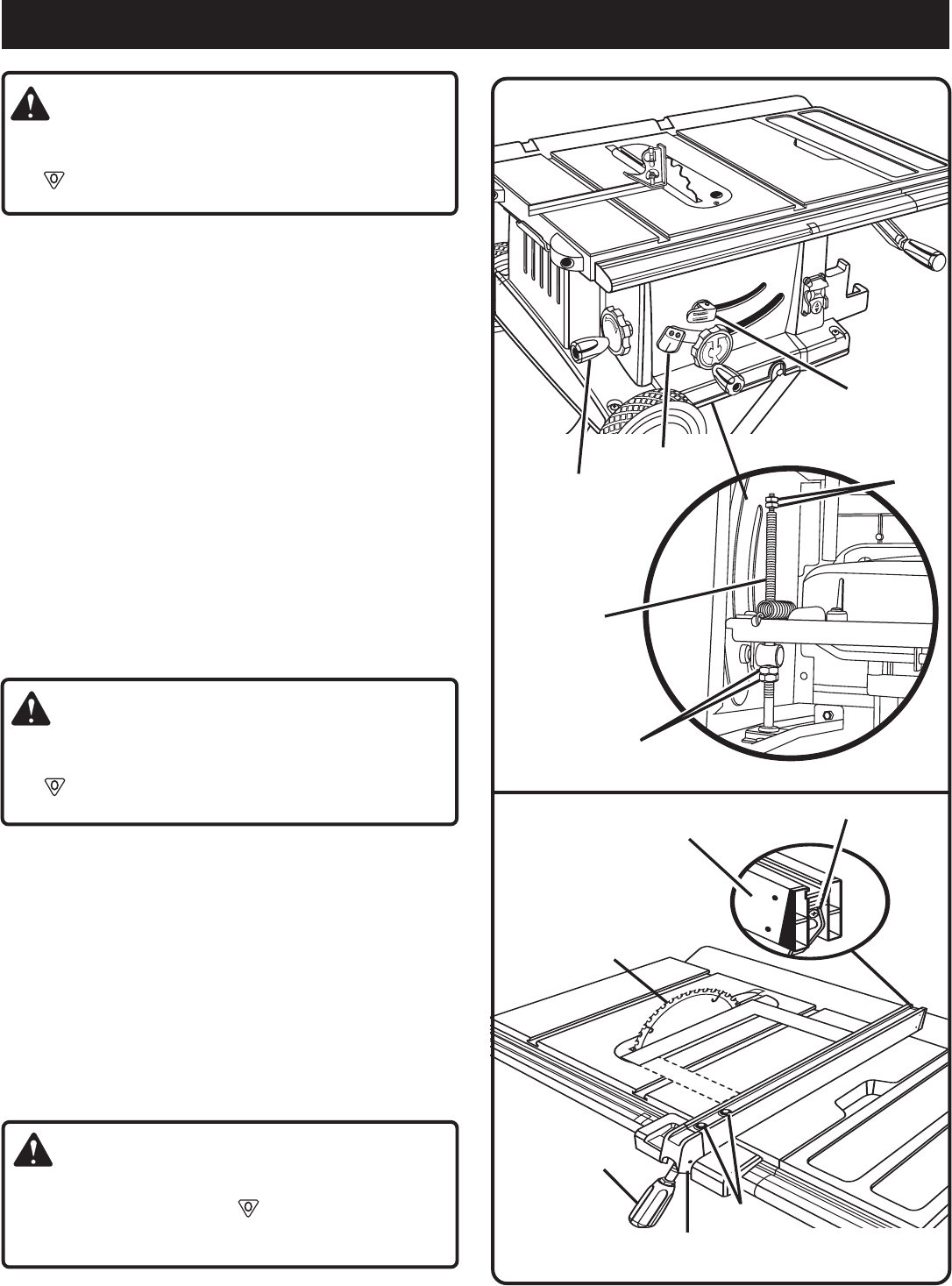
TO SET BLADE AT 0
° OR 45°
See Figure 40.
The angle settings of your saw have been set at the factory
and, unless damaged in shipping, should not require setting
during assembly. After extensive use, it may need to be
checked.
If the blade is not perfectly vertical (0°), loosen the nuts on
the stop bolt inside the cabinet, position the blade, adjust
the stop bolt, then retighten nut.
See Figure 40, insert.
Turn the blade adjusting handle until the bottom of the
blade has moved completely to the left side of the slot.
Lock the angle by pushing the bevel locking lever.
If the blade is not an exact 45°, loosen the nuts on the stop
bolt inside the cabinet, position the blade, adjust the stop
bolt, then retighten lock nut.
See Figure 40, insert.
Make a test cut.
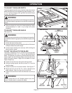
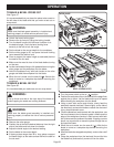
TO CHECK THE ALIGNMENT OF THE RIP
FENCE TO THE BLADE
See Figure 41.
WARNING:
Before performing any adjustment, make sure the tool is
unplugged from the power supply and the switch is in the
off ( ) position. Failure to head this warning could result
in serious personal injury.
Raise the locking handle to permit the rip fence to be
moved.
Place a framing square beside the blade and move the rip
fence up to the square. Take the dimension on the rip
scale.
Move the fence back and turn the framing square 180° to
check the other side.
If the two dimensions are not the same, loosen the two
screws on the fence and align it.
Retighten the two screws.
Make two or three test cuts on scrap wood. If the cuts are
not true, repeat the process.
WARNING:
Before plugging the saw back in to make test cuts, make
sure the switch is in the off ( ) position and the blade
guard is in place. Failure to do so may result in serious
injury.
MAINTENANCE
BEVEL
LOCKING LEVER
BEVEL
HANDLE
BEVEL
INDICATOR
STOP BOLT
NUTS
Fig. 40
NUTS
BLADE
LOCKING
HANDLE
RIP FENCE
Fig. 41
SCREWS
RIP
FENCE
CLAMP SCREW