


Compact® NSF and NSJ 150 to 600 A Circuit Breakers
Section 4—Trip Units
© 1995–2003 Schneider Electric All Rights Reserved
15
Options for
Electronic Trip
Unit STR53UP
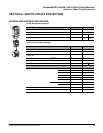
Equipment Ground-fault Protection (T)—see (6) and (7), page 14
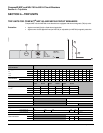
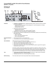
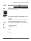
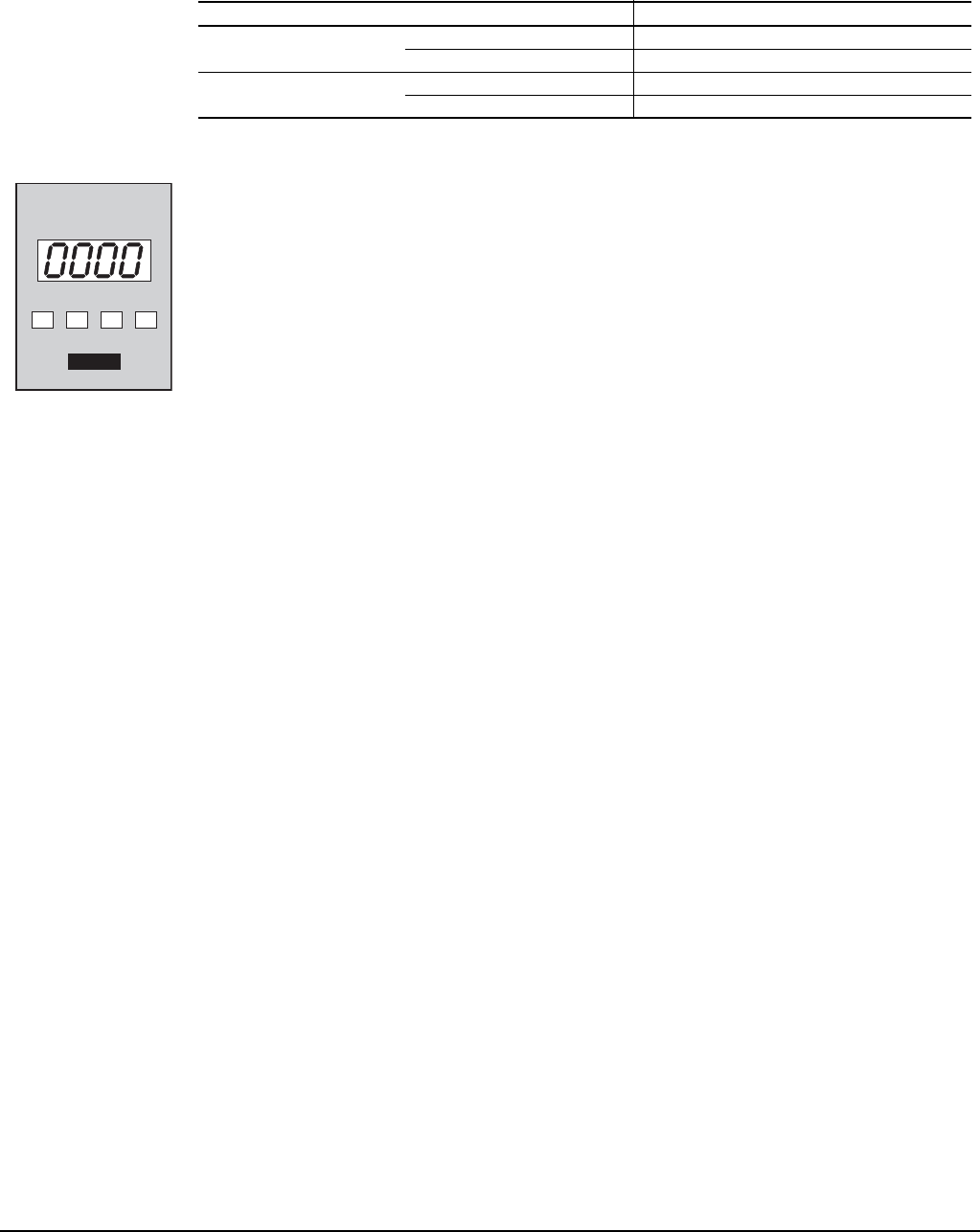
Ammeter (I) A digital display continuously indicates the current of the phase with the greatest load. By pressing a
scroll button, it is also possible to display successively the readings of I1, I2, I3 and I neutral. LEDs
indicate the phase for which the current is displayed.
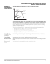
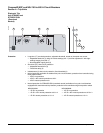
Zone-selective
Interlocking (ZSI)
A number of circuit breakers are interconnected one after another by a pilot wire. In the event of a
short-time or earth fault:
• If a given trip unit STR53UP detects the fault, it informs the upstream circuit breaker which applies
the set time delay
• If the trip unit STR53UP does not detect the fault, the upstream circuit breaker trips after its shortest
time delay
In this way, the fault is cleared rapidly by the nearest circuit breaker. In addition, thermal stresses on
the circuits are minimized and time discrimination is maintained throughout the installation.
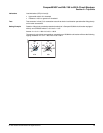
Opto-electronic
Outputs
The use of opto-transistors ensures total isolation between the internal circuits of the trip unit and the
circuits wired by the user.
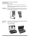
Communication
(COM)
Transmission of the following data to Digipact
®
distribution monitoring and control modules:
• Settings
• Phase and neutral currents (rms values)
• Highest current of the three phases
• Overload condition alarm
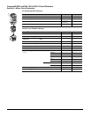
Possible
Combinations
• I
• T
• I + T
• I + COM
• I + T + COM
• ZSI
• ZSI + I
• ZSI + T
• ZSI + I + T
• ZSI + I + COM
• ZSI + I + T + COM
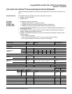
Type
Residual Current
Tripping threshold
Ig Adjustable (8 Settings) 0.2–1 x In
Accuracy ± 15%
Tripping time (ms)
Max. overcurrent time before tripping (Tg) Adjustable (4 Settings + Constant I
2
t Function) 60, 140, 230, 350
Total Breaking Time -140, -230, -350, -500
A
In I1 I2 I3
06153068