


Compact® NSF and NSJ 150 to 600 A Circuit Breakers
Section 7—Mounting Configurations
© 1995–2003 Schneider Electric All Rights Reserved
22
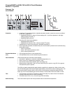
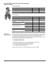
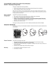
The plug-in configuration makes it possible to:
• Extract and/or rapidly replace the circuit breaker without having to touch connections
• Allow for addition of future circuits at a later date
When the circuit breaker is in the connected position, the primary voltage is fed through the circuit
breaker by means of multiple finger disconnects. Control voltage of internal accessories is provided
through secondary disconnects.
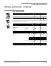
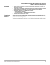
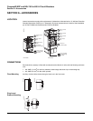
Parts of a Plug-in
Configuration
Compact
®
circuit breaker (fixed mounted)
• Set of power and secondary disconnects that are added to the circuit breaker
• Plug-in base for mounting through a front panel or on rails
• Safety trip, to be installed on the circuit breaker, which causes automatic tripping if the circuit
breaker is ON before engaging or withdrawing it; the safety trip does not prevent circuit breaker
operation, even when the circuit breaker is disconnected
• Mandatory short terminal shields
The plug-in mounting is Listed under UL file E113555 and Certified under CSA file LR 69561.
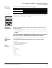
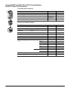
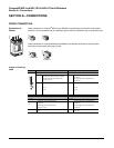
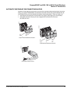
DRAWOUT MOUNTING
The chassis is made up of two side plates installed on the base and two other plates mounted on the
circuit breaker.
Chassis Functions All functions of the plug-in base, plus:
• Disconnected position: the power circuits are disconnected, the circuit breaker is simply
"withdrawn" and may still be operated (on, off, push-to-trip)
• Circuit breaker may be locked using 1 to 3 padlocks—diameter 0.19 to 0.31 inch (5 to 8 mm)—to
prevent connection
• Auxiliaries can be tested using manual auxiliary connector
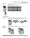
Mounting • On a backplate, through a front panel or on rails
• Horizontally or vertically
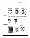
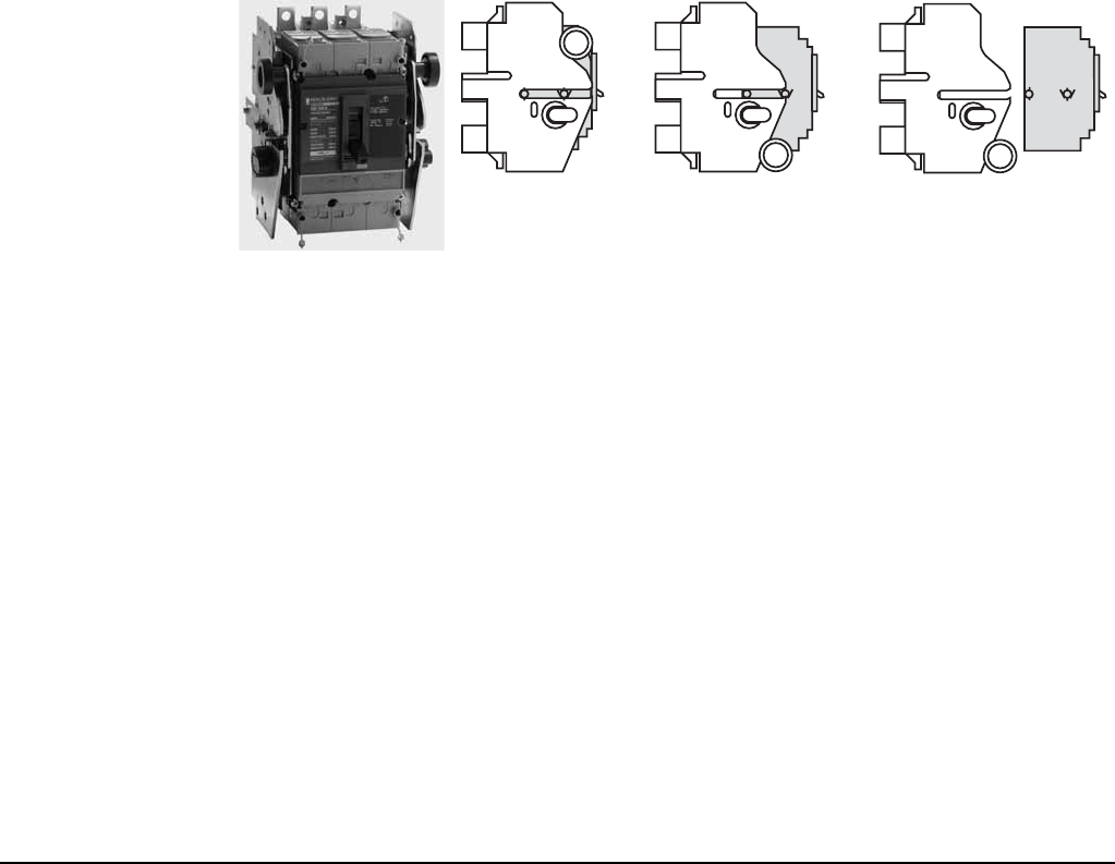
Connected
RemovedDisconnected
06153079
06153080