


Compact® NSF and NSJ 150 to 600 A Circuit Breakers
Table of Contents
© 1995–2003 Schneider Electric All Rights Reserved
3
TABLE OF CONTENTS
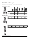
THE COMPACT
®
CIRCUIT BREAKER LINE .......................................................................................4
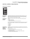
GENERAL CHARACTERISTICS .......................................................................................................... 5
Compliance with Standards .............................................................................................................5
CIRCUIT BREAKERS ........................................................................................................................... 8
Ratings and Interrupting Ratings ..................................................................................................... 8
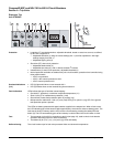
TRIP UNITS ........................................................................................................................................ 10
Trip Units for Compact
®
NSF150 and NSF250 Circuit Breakers .................................................. 10
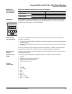
Trip Units for Compact
®
NSJ400 and NSJ600 Circuit Breakers ................................................... 11
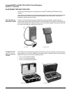
Electronic Trip Unit Test Kits ......................................................................................................... 16
SWITCHES ......................................................................................................................................... 17
Ratings and Interrupting Ratings ................................................................................................... 17
MOTOR CIRCUIT PROTECTORS ..................................................................................................... 19
Ratings and Interrupting Ratings ................................................................................................... 19
MOUNTING CONFIGURATIONS ....................................................................................................... 21
Fixed Mounting .............................................................................................................................. 21
Connections .................................................................................................................................. 21
Plug-in Mounting ........................................................................................................................... 21
Drawout Mounting ......................................................................................................................... 22
CONNECTIONS ................................................................................................................................. 24
Front Connection ........................................................................................................................... 24
Rear Connection ........................................................................................................................... 25
ACCESSORIES ..................................................................................................................................26
Location ......................................................................................................................................... 26
Connections .................................................................................................................................. 26
Automatic Secondary Disconnecting Blocks ................................................................................. 27
Auxiliary and Alarm Switches ........................................................................................................ 28
Shunt Trip and Undervoltage Trip ................................................................................................. 30
Motor Operator .............................................................................................................................. 31
Rotary Operating Handles ............................................................................................................. 33
Cable Operating Handles ..............................................................................................................35
Locking Systems ........................................................................................................................... 36
Interlocking Accessories ................................................................................................................37
Front Panel Escutcheons .............................................................................................................. 39
DIMENSIONS ..................................................................................................................................... 41
Fixed Mounted ...............................................................................................................................41
Plug-in and Drawout Mounting ...................................................................................................... 43
Cable Operating Handles ..............................................................................................................47
Rotary Operating Handles ............................................................................................................. 48
Front Accessories ..........................................................................................................................51
Interlocking Systems .....................................................................................................................52
CONNECTION DIMENSIONS ............................................................................................................53
WIRING DIAGRAMS .......................................................................................................................... 55
SUPPLEMENTARY TECHNICAL INFORMATION ............................................................................. 57
Reflex Tripping .............................................................................................................................. 62
Let-through Curves ........................................................................................................................63
Current Limiting Curves ................................................................................................................. 65
UL 489 Test Procedure .................................................................................................................67
IEC 947-2 Test Procedure ............................................................................................................. 70
Routine and Maintenance Guidelines ........................................................................................... 73