


Compact® NSF and NSJ 150 to 600 A Circuit Breakers
Section 12—Wiring Diagrams
© 1995–2003 Schneider Electric All Rights Reserved
55
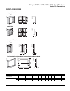
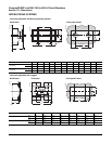
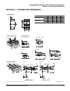
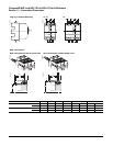
SECTION 12—WIRING DIAGRAMS
I
d
82 84
SDE
81
12 14
OF1
11
92 94
SD
91
C1
12 14
92 94
C1
C2
11
91C2
352 354
CD
351
314
312
CE
31
1
MX
D1
D1
D4
D4
22 24
OF2
21
21
22 24
MN
72 74
71
84
RD
GN
VT
YE
VT
YE
RD
GN
WH
VT
GY
GY
VT
YE
YE
(2)
SDV
OR
BL
BL
GY
GY
(1)
32 34
OF3
31
32 24
31
Z11 e
+
T1
R1
Z12
e
-
T2
R2
WH
RD
BL
GY
VT
YE
BK
GN
OR
trip unit (3)
MT
BK (4)
B2 A2 A4 B4
A1 L1
A1
L1
BK
GN
GN (4)
A2 B4A4
WH
OR
BL
I
d
82 84
SDE
81
12 14
OF1
11
92 94
SD
91
C1
12 14
92 94
C1
C2
81
11
91C2
352 354
CD
351
314
312
CE
31
1
MX
D1
D1
D4
D4
22 24
OF2
21
21
22 24
MN
72 74
71
CAO1
CAF2CAF1
BK
RD
YE
VT
BK
RD
GY
82 84
RD
GN
VT
YE
VT
YE
RD
GN
WH
VT
GY
GY
VT
YE
YE
(2)
SDV
OR
BL
BL
GY
GY
(1)
32 34
OF3
31
32 24
31
Z11 e
+
T1
R1
Z12
e
-
T2
R2
WH
RD
BL
GY
VT
YE
BK
GN
OR
trip unit (3)
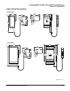
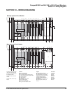
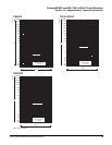
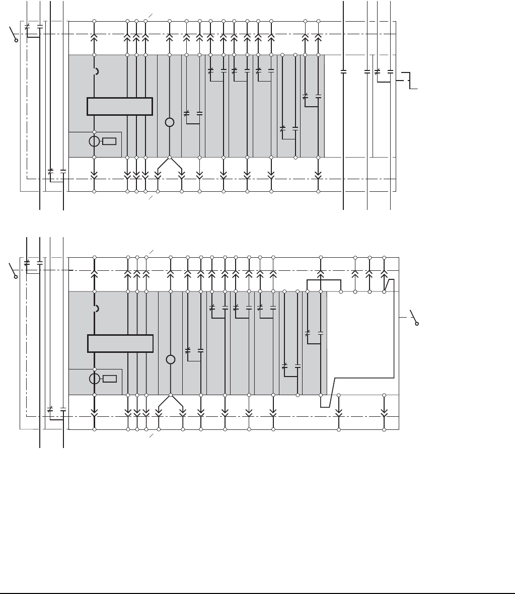
Manually-operated Circuit Breaker
All schemes are shown without
the control voltage present, all
devices open and relays in the
de-energized position.
Switches CD, CE: on drawout
chassis.
Switches CAO, CAF: on rotary
handle.
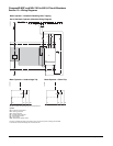
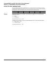
Motor-operated Circuit Breaker
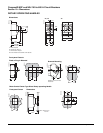
Symbols
CAF = early-make switch
CAO = early-break switch
CE = "connected" position indication switch
CD = "disconnected" position indication switch
MN = undervoltage trip
MT = motor operator
MX = shunt trip
OF = position indication switch
SD = trip indication switch
SDE = overcurrent trip switch
SDV = ground-fault indication switch
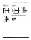
Legend
(1) Undervoltage or shunt trip
(2) For plug-in/drawout versions, SDV
and OF2 switches can be installed
together, but only one of them will be
connected through automatic
secondary disconnecting blocks
(3) Options are only installed on trip
unit STR53UP
(4) Wiring supplied, mandatory to
connect
Color code
VT: Purple
YE: Yellow
RD: Red
BK: Black
GN: Green
GY: Grey
WH: White
OR: Orange
BL: Blue
06153203
06153202