


Compact® NSF and NSJ 150 to 600 A Circuit Breakers
Section 13—Supplementary Technical Information
© 1995–2003 Schneider Electric All Rights Reserved
74
Insulation
Resistance Tests
When a circuit breaker is subjected to severe operating conditions, an insulation resistance test should
be performed as indicated in NEMA standard publication No. AB4-1996. An insulation resistance test is
used to determine the quality of the insulation between phases and phase-to-ground. The resistance
test is made with a dc voltage higher than the rated voltage to determine the actual resistance of the
insulation.
The most common testing method employs a "megger" type instrument. A 1000 V instrument will
provide a more reliable test because it is capable of detecting tracking on insulated surfaces.
Resistance values below one megohm are unsafe and should be investigated. An insulation test should
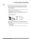
be made:
• Between line and load terminals of individual poles with the circuit breaker contacts open
• Between adjacent poles and from poles to the metallic supporting structure with the circuit breaker
contacts closed. The latter test may be done with the circuit breaker in place after the line and load
conductors have been removed, or with the circuit breaker bolted to a metallic base which simulates
the in-service mounting.
Electrical Tests These tests require equipment for conducting pole resistance, overcurrent and instantaneous tripping,
in accordance with NEMA Standard publication No. AB4. They are not within the scope of normal field
operation.