


TOOLS REQUIRED
• Phillips screwdriver.
° Small or medium sized adjustable wrench
(or a set of nutdrivers).
° Electrical with 5/32" drill bit.
• Hammer
ROUTER TABLE
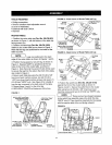
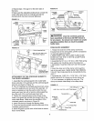
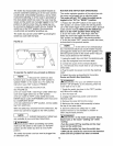
1. Position the router table top (Part No. 29LCN-981)
as shown in Figure 1, with the bottom of the table top
facing toward you.
2. Position the table legs (Part No. 29LCN-1283)
relative to the router table top as shown in Figure 1.
Note that the legs are positioned to the inside of the
table top sides.
B
I NOTE I Legs are positioned to the back
l
edge of the router table, as shown in Figures 1 and 3.
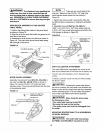
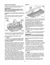
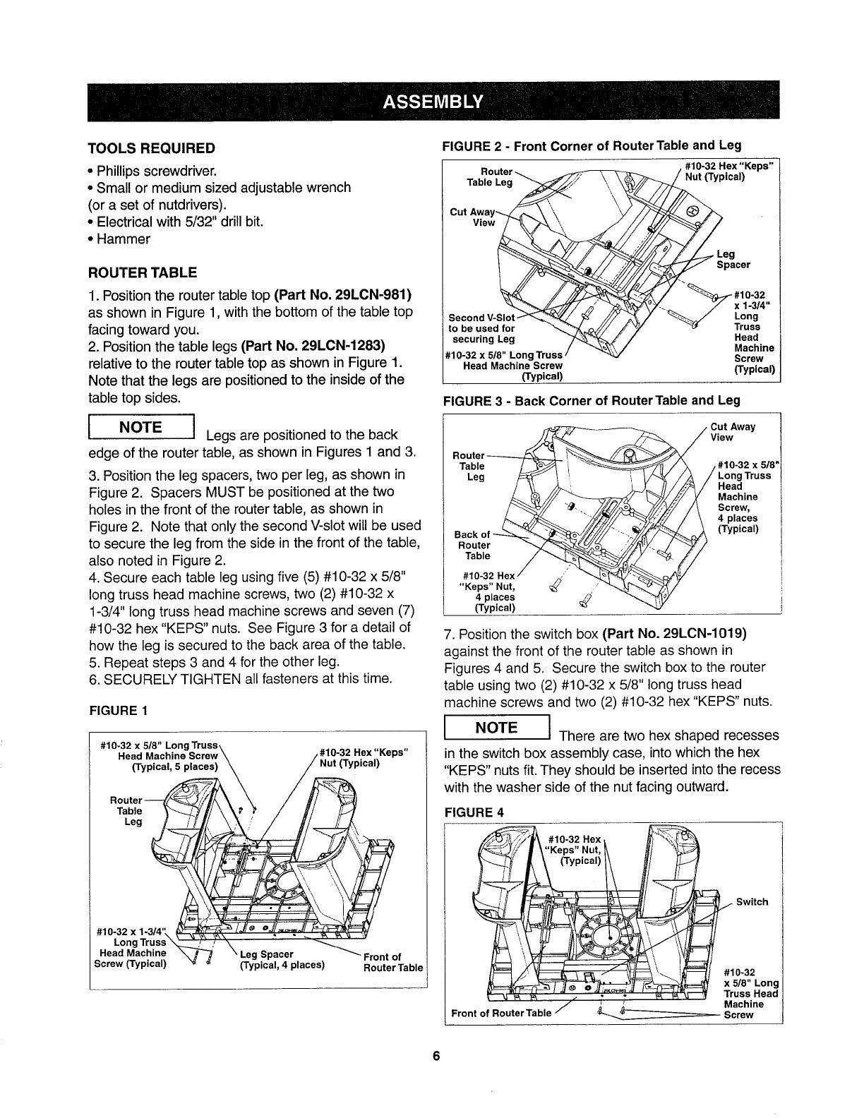
3. Position the leg spacers, two per leg, as shown in
Figure 2. Spacers MUST be positioned at the two
holes in the front of the router table, as shown in
Figure 2. Note that only the second V-slot will be used
to secure the leg from the side in the front of the table,
also noted in Figure 2.
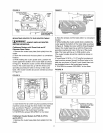
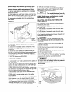
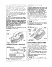
4. Secure each table leg using five (5) #10-32 x 5/8"
long truss head machine screws, two (2) #10-32 x
1-3/4" long truss head machine screws and seven (7)
#10-32 hex "KEPS" nuts. See Figure 3 for a detail of
how the leg is secured to the back area of the table.
5. Repeat steps 3 and 4 for the other leg.
6. SECURELY TIGHTEN all fasteners at this time.
FIGURE 1
I #10-32 x 5/8" LongTruss\ ,,.
Head Machine Screw\ /#10-32 Hex r.eps"
Router_ \(Typical' 5 places)k_ / ///_ Nut (Typmal)
Table _--_'_// \ k_' _ / _'/ /_
•e,
-32xl- _ k_
#1°LongT-uss .; " _
Head Mac_F" _ \ Leg Spacer . _ Front of
_crew (=yp=cai) '_ _ (Typmal, 4 places) RouterTable
FIGURE 2 - Front Corner of Router Table and Leg
Router _
Table Leg _/ \\\\
Cut Away_\ "
View_
Second V-Slot-_'_;_._ _ ///
to be used for _ik_/'/ J
securing Leg _'
#10-32 x 5/8" Long Truss /
Head Machine Screw
(Typical)
10-32 Hex "Keps" ]
ical) /
_///fY 7/I'7" Leg
Spacer
.10-32
_k_Y-. 7 x 1-3/4"
/v -_ Long
/ "_ Truss
Head
Machine
Screw
(Typical)
FIGURE 3 - Back Corner of Router Table and Leg
Cut Away
View
Table
Leg
Router
Table
#10-32 Hex ,
"Keps" Nut,
4 places
(Typical)
#10-32 x 5/8'
Long Truss
Head
Machine
Screw,
4 places
(Typical)
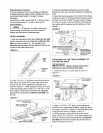
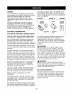
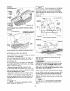
7. Position the switch box (Part No. 29LCN-1019)
against the front of the router table as shown in
Figures 4 and 5. Secure the switch box to the router
table using two (2) #10-32 x 5/8" long truss head
machine screws and two (2) #10-32 hex "KEPS" nuts.
I
I NOTE I There are two hex shaped recesses
I
in the switch box assembly case, into which the hex
"KEPS" nuts fit. They should be inserted into the recess
with the washer side of the nut facing outward.
FIGURE 4
#10-32 Hex t
'Keps" Nut, _ H/
(Typical)/_ l/ _,
- _ _ Switch#10-32
x 5/8" Long
Truss Head
/
Machine
Front of Router Table _--....___ Screw
6