


Other Brands of Routers
It will be necessary for you to purchase a Craftsman
Professional Router Adapter Plate, #25333, from your
local Sears Retail Outlet, or through the Sears
Catalogue.
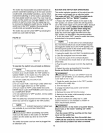
Routers with a total overall height of 13 inches or less,
and a base diameter of 7 inches or less can be
accommodated.
m
I NOTE I Because of vibration that occurs
i
during routing, occasionally check the screws to
assure that they have not become loose.
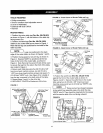
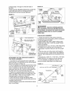
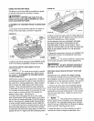
FENCE ASSEMBLY
1. Slide the adjustable jointing fence (Part No. 291.-758)
into the pocket on the router table fence (Part No. 29L-
994), as shown in Figure 10. The V-guide on the
adjustable jointing fence will mate with and slide on the
V-guide in the router table fence.
FIGURE 10
Router
Table
Fence
Adjustable
Jointing
Fence
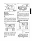
2. Insert a 1/4"-20 x 1" long hex head bolt through the
hole with a hex recess in the router table fence, and
through the slot in the adjustable jointing fence as
shown in Figure 11. While holding the head of the bolt
in the hex recess, place a 9/32" I.D. x 3/4" O.D. x 1/16"
thick washer over the bolt, and thread the adjustable
jointing fence clamping knob (Part No. 29L-659) onto
the bolt.
FIGURE 11
Adjustable Jointing Fence_
Clamping Knob_
9132" I.D. x 314" O.D. __ _,."_
x 1/16" Thick Washer _ _
Adjustable
Jointing
1/4-20 x 1" Long Fence
Finished Hex Head Bolt
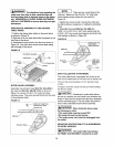
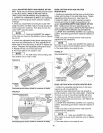
3. Push the adjustable jointing fence into the router
table fence as far as it will go and tighten the clamping
knob.
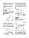
4. Assemble the fence guide to the bottom of the fence
using two #10-32 x 7/8" long panhead machine screws
and two #10-32 hex "KEPS" nuts, as shown in Figure
12. (The nut portion of the hex "KEPS" nut fits into the
hex recess, with the washer portion facing out of the
recess.)
FIGURE 12
#10-32 x 7/8" Long
Panhead Machine Screw "_ !
NOTE: Orientation of Front
in Fence must be toward the Front
of the RouterTable Fence
Fence Guide
#10-32 Hex "KEPS" Nut-__
(Typical)
Surface of
Fence Guide must
be flush with Back
Surface of Router
Table Fence
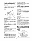
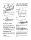
ATTACHMENT OF THE FENCE ASSEMBLY TO
THE ROUTER TABLE
I _'WARNINGI Always unplug router before
attaching or removing fence from table,
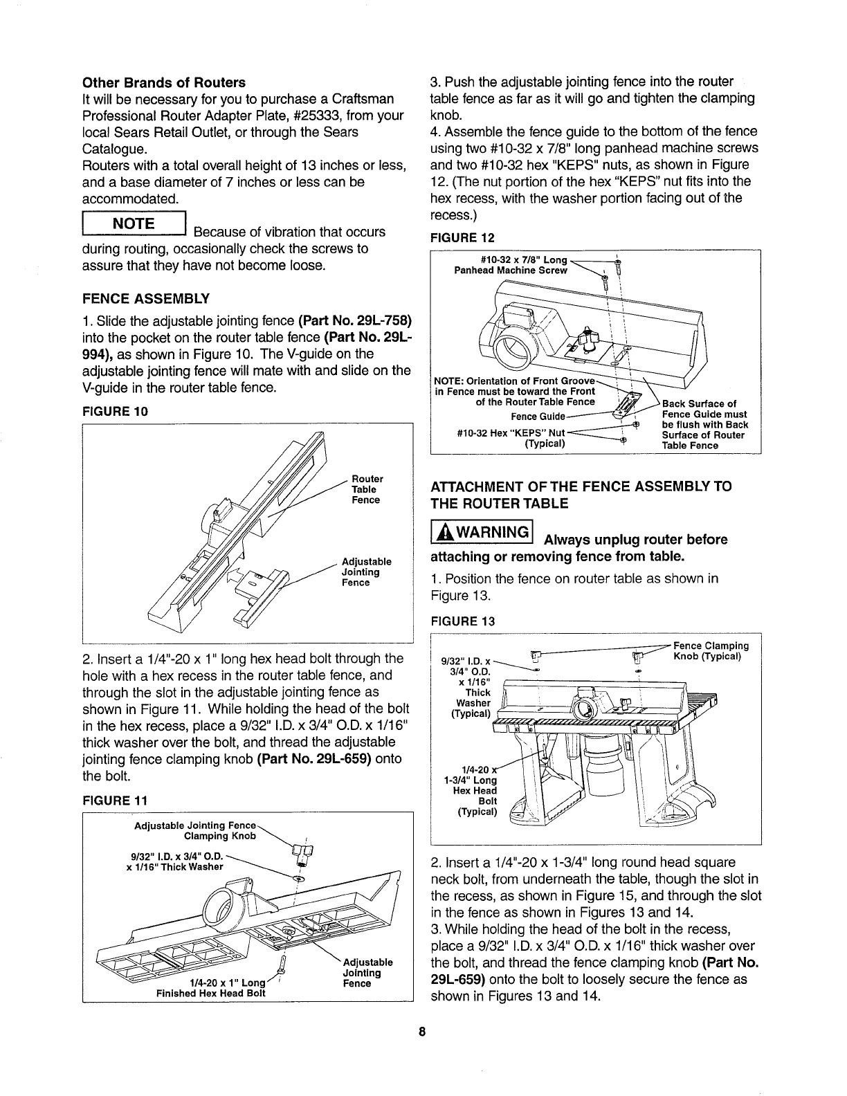
1. Position the fence on router table as shown in
Figure 13.
FIGURE 13
I _ Fence Clamping
9/32" I.D. x _ 1_"_ _3_ Knob (Typical)
3/4" O.D. _
x 1/16" / i
Thick _ '__ -'._77k !, ft_
Washer __t_', _--_/
(Typical) __
-' Y I,!
1-3/4" Long / i _'_"_\ I/ I I! /V,-',%_
Rex Head I ! _ ! _<--_'_,
Bol_i/_ _; ,:.s_'_. _
(Typ,ca,)
2. Insert a 1/4"-20 x 1-3/4" long round head square
neck bolt, from underneath the table, though the slot in
the recess, as shown in Figure 15, and through the slot
in the fence as shown in Figures 13 and 14.
3. While holding the head of the bolt in the recess,
place a 9/32" I.D. x 3/4" O.D. x 1/16" thick washer over
the bolt, and thread the fence clamping knob (Part No.
29L-659) onto the bolt to loosely secure the fence as
shown in Figures 13 and 14.
8