


12
6
14
12
10
8
®
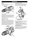
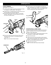
n Make sure the latches on each side of your battery
pack snap in place and battery pack is secured in drill
before beginning operation.
CAUTION: When placing battery pack in your drill,
be sure raised rib on battery pack aligns with groove
inside drill and latches snap into place properly.
Improper assembly of battery pack can cause damage
to internal components.
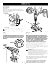
TO REMOVE BATTERY PACK
n Lock switch trigger on your drill by placing the direction
of rotation selector in center position. See Figure 5.
n Locate latches on side of battery pack and depress to
release battery pack from your drill. See Figure 4.
n Remove battery pack from your drill.
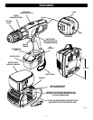
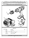
TWO SPEED
GEAR TRAIN (HI-LO)
SWITCH
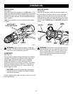
See Figure 2.
To turn your drill ON, depress the switch trigger. To turn it
OFF, release the switch trigger.
TO INSTALL BATTERY PACK
n Lock switch trigger on your drill by placing the direction
of rotation selector in center position. See Figure 5.
n Place battery pack in your drill. Align raised rib on
battery pack with groove inside drill. See Figure 4.
Fig. 4
BATTERY
PACK
LATCHES
Fig. 2
VARIABLE SPEED
This tool has a variable speed switch that delivers higher
speed and torque with increased trigger pressure. Speed is
controlled by the amount of switch trigger depression.
Note: You might hear a whistling or ringing noise from the
switch during use. Do not be concerned, this is a normal
part of the switch function.
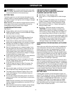
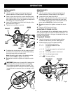
TWO-SPEED GEAR TRAIN
See Figure 3.
Your drill has a two-speed gear train designed for drilling
or driving at LO (1) or HI (2) speeds. A slide switch is
located on top of your drill to select either LO (1) or HI (2)
speed. When using drill in the LO (1) speed range, speed
will decrease and unit will have more power and torque.
When using drill in the HI (2) speed range, speed will
increase and unit will have less power and torque. Use LO
(1) speed for high power and torque applications and HI
(2) speed for fast drilling or driving applications.
OPERATION
HI
SPEED
Fig. 3
VARIABLE SPEED
SWITCH TRIGGER
FORWARD/REVERSE
SELECTOR
1
2
DEPRESS LATCHES TO
RELEASE BATTERY PACK
LO
SPEED