


-36-
W1756/W1757 43" Wide-Belt Sander
SERVICE
Oscillation Timing
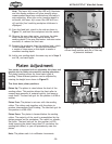
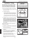
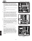
When the oscillation is correctly adjusted, the sanding
belt oscillates to the left and to the right at the same
speed. If the sanding belt makes contact with a limit
switch, as shown in Figure
34, the emergency braking
system will activate and stop the sander immediately.
To check the sanding belt oscillation, do these steps:
1. Be sure the sanding belt is properly installed and the
belt tension knob is
ON.
2. Turn ON the sanding belt.
— If the belt oscillates without contacting the limit
switches, but the oscillation time to the left and
right are
NOT equal, proceed to Step 6, Page 37.
— If the belt tracks away from the air fork and air
jet, triggering the limit switch, continue with
Step
3.
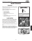
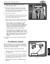
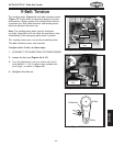
3. An adequate stream of air through the air fork gap
(Figure 35) is essential for proper oscillation. If the
jet of air is weak through the gap, the belt will track
away from the controller and into the limit switch
on the opposite end of the roller. The pivot action of
the upper roller, and the resulting oscillation of the
belt, are dependent upon adequate airflow through
the air fork gap.
To set the correct amount of airflow through the air
fork gap, do these steps:
1. DISCONNECT THE SANDER FROM THE POWER SOURCE!
2. Remove the sanding belt, then turn the belt tension
knob to the tensioned position.
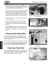
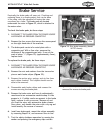
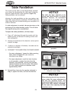
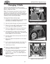
3. Loosen the lock nut on the airflow adjustment knob
(Figure 36).
4. Turn the airflow adjustment knob (Figure 36)
clockwise until the airflow is completely
OFF. The
upper roller should pivot to the right.
5. Slowly turn the airflow adjustment knob
counterclockwise, and continue turning up the air
pressure until the roller pivots to the left.
N
ote: The basic factory setting is established by
backing out the knob until it stops, then turning it
3
1
⁄2 turns.
NOTICE
The oscillation adjustments have been
performed at the factory and should
require no further attention. However,
we recommend verifying the settings.
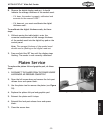
Figure 34. Improper oscillation.
Limit
Switches
Sanding Belt
Sander Outline
(Top View)
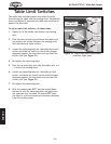
Figure 35. Air jet and air fork assembly.
Oscillation Controller Gap
Air Fork
Figure 36. Airflow adjustment knob.
Lock Nut
Air Jet