


-43-
W1756/W1757 43" Wide-Belt Sander
SERVICE
Feed Belt Replacement
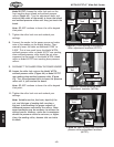
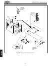
To remove the feed belt, use Figure 53 on Page 44 and
match the number with the steps below:
1. Raise the table up so the conveyor belt is
approximately two-inches away from the sanding
roller or platen, and then
DISCONNECT THE SANDER
FROM THE POWER SOURCE!
2. Remove the gearbox mounting bracket, and with an
assistant's help, slide the motor and gearbox from
the roller shaft and lower it to the floor.
Note: Do not loosen the two vibration dampener
washers shown
in Figure 53.
3. Remove two table height limit switches.
4. Remove both lower access panels.
5. Remove the left and right table guides.
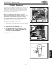
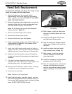
6. Using a permanent marker, mark all four lead screw
flange positions (
Figure 52), and remove all hex
bolts from the flanges.
7. Insert two 2x4x8' wooden studs under the table to
support the table, and then (with help) lift the table
slightly and move it out of the rear of the machine.
8. Disconnect the limit switch, remove all mounting
screws, and remove
the emergency stop push-panel
assembly.
9. Turn both tracking adjustment bolts counter-
clockwise five turns, remove one roller support, and
slide the drum out of the table assembly.
10. Remove the old feed belt, inspect rollers, bearings,
and table for wear and replace as required.
11. Install the new feed belt.
Note: The belt is non-directional.
12. Install the front roller, the roller support, and turn
both tracking adjustment bolts clockwise
equally so
the conveyor belt becomes taught and does not hang
loose. DO NOT OVERTIGHTEN the belt.
13. With a helper, install the table from
the rear in a similar fashion as it was
removed.
14. Install the table guides and the left
and right lower access panels
.
15. Align the lead screw flanges with the
marks made in Step 6, and install the
hex bolts.
16. Install and adjust the table height
limit switches (refer to
Page 34).
17. With a helper, install the gearbox,
vibration dampener washers, and
mounting bracket.
18. Install the emergency stop push panel
assembly and the limit switch.
19. Start the conveyor motor and turn the
conveyor tracking bolts as required
until the conveyor belt tracks straight
without loading up on one side of the
table.
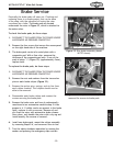
Figure 52. Marking lead screw for
reassembly.
Timing Mark