


a
b
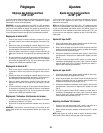
FIG. 4
24
.
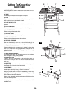
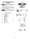
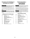
Getting To Know Your
Table Saw
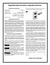
1. POWER SWITCH
Has a design feature allowing the tool to be locked in the OFF (“O”)
position.
2. TABLE
P
rovides large working surface to support workpiece.
3. BASE
Supports table saw. For additional stability, holes are provided in
base to bolt the saw to a workbench or stand.
4. BLADE ANGLE LOCK
Locks the tilt mechanism after the blade is adjusted to desired
position.
5. ELEVATION WHEEL
Elevates or lowers the blade at all angles from 0 to 45 degrees.
6. BLADE TILT SCALE
Shows the degree the blade is tilted.
7. RIP FENCE SCALE
Shows the distance from the blade to rip fence.
8. MITER GAUGE SCALE
Shows the degree the workpiece is being mitered.
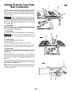
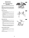
9. RIP FENCE STORAGE
Conveniently stores rip fence on two pads on the right side of base
when not in use. Simply align hole on fence with locating pin on
front pad, and press fence down into it’s storage position as shown.
10. MITER GAUGE STORAGE
Conveniently stores miter gauge on the left side of the base when
not in use. Simply insert miter gauge bar into rectangular hole on
right side of base, and push the miter gauge fully into it’s storage
position as shown.
11. ANTI-KICKBACK PAWLS
The anti-kickback pawls are designed to prevent the workpiece
from “kicking back” during cutting operation.
12. SAWDUST PORT
The dust port can accommodate a dust collection system or
vacuum hose hookup to aid in the removal of sawdust from the
work area.
13. SPLITTER
The splitter aligned with the saw blade and anti-kickback pawls is
intended to stop a kickback once it has started.
14. RIP FENCE
Exclusive Self-Aligning, Quick-Set rip fence can be easily moved or
locked in place by simply raising or lowering lock handle.
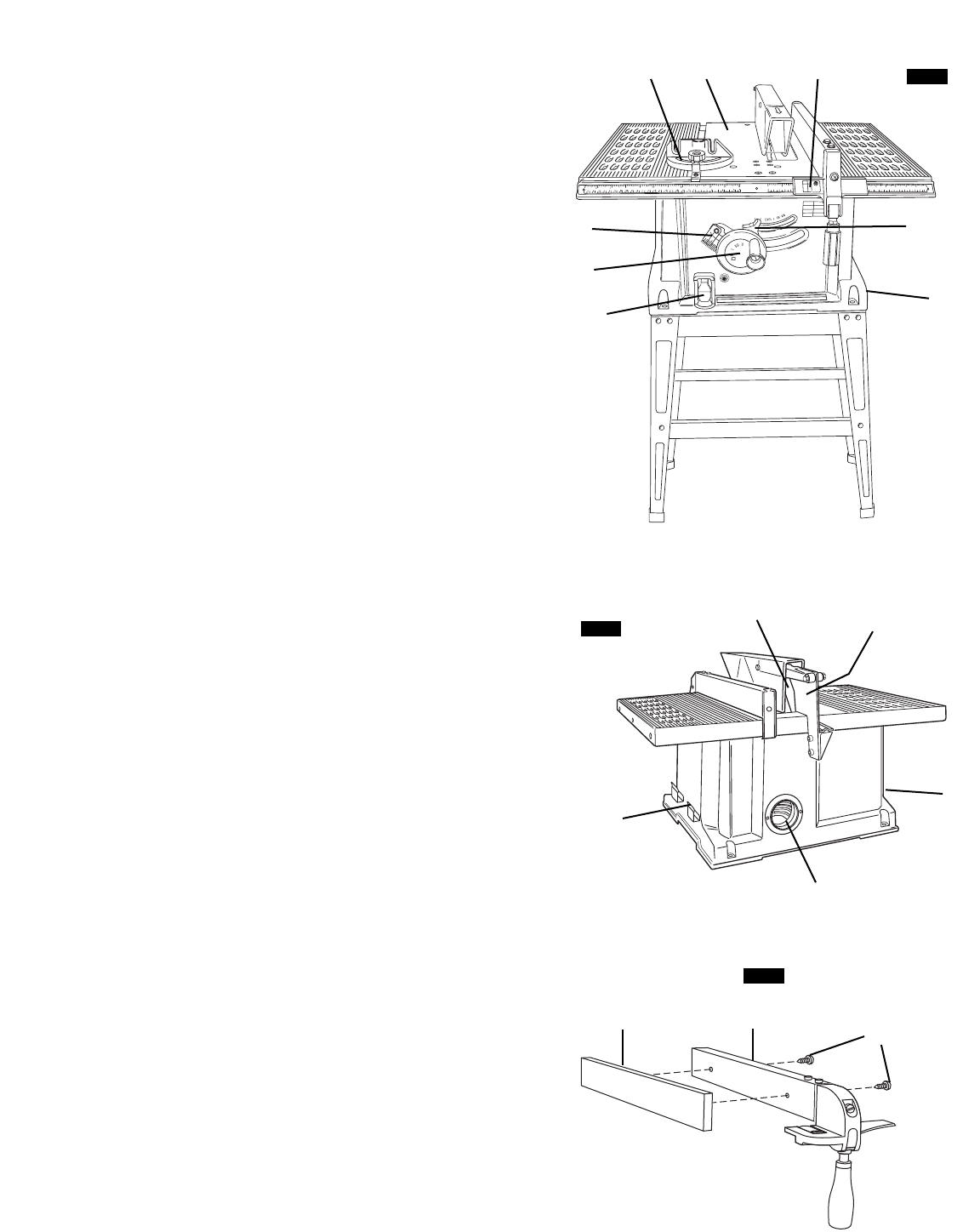
Holes are provided in the rip fence
14 for attaching a wood facing
(a) ( Fig. 3). Wood facing should be used when making cuts using
dado blades, or ripping thin materials.
Select a piece of smooth straight wood approx. 3/4" thick and the
same size as the rip fence.
Attach it to the fence with two round head No. 10 wood screws 1- 5/8"
long
(b) (Fig. 4).
14
FIG. 3
FIG. 2
1
5
6
12
9
10
11
13
3
4
287